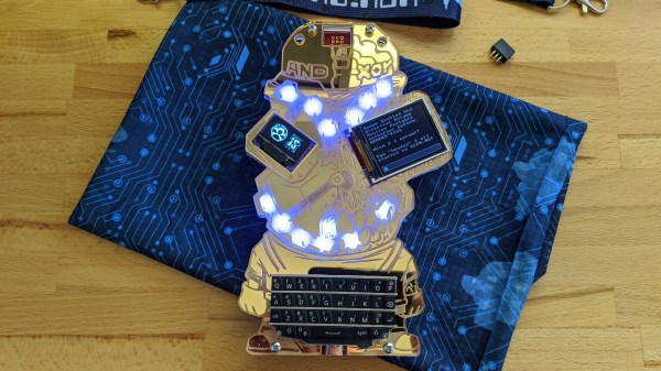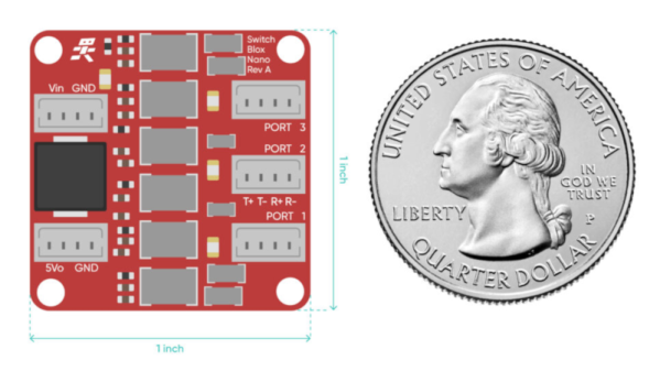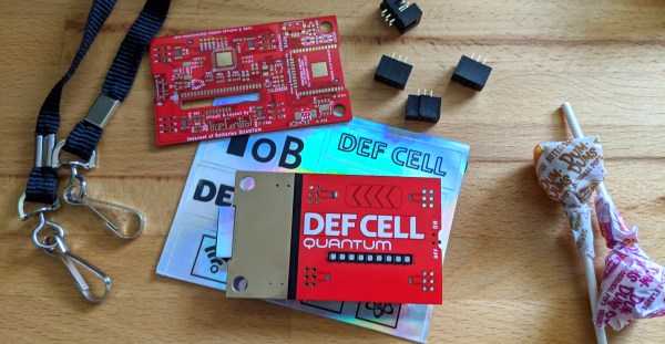
Our friends in the Whiskey Pirates crew sent me the unofficial DEF CON badge they built this year. The Internet of Batteries QUANTUM provides power and connectivity to the all-important add-on badges of DC28. The front of the badge is absolutely gorgeous to the point I don’t really want to solder on my add-on headers and disrupt that aesthetic.
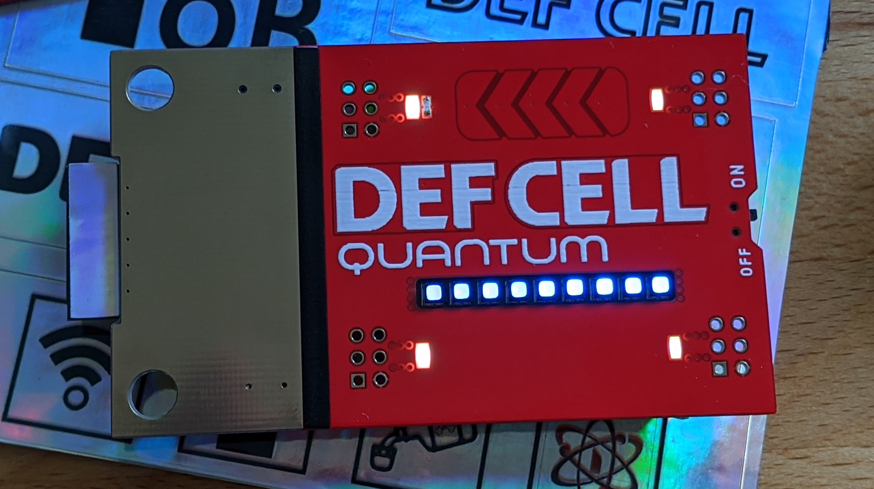
The gold-plated copper makes for a uniformed and reflective contrast to the red solder mask which occupies the majority of the front. Here we see the great attention to detail that [TrueControl] includes in his badges. The white stripe of silk screen separating the two colors is covered by some black detailing tape that looks much better than the white.
 The antenna of the ESP32 module poking out the underside of the gold cover end of the badge gets its own rectangle of the holographic sticker material, the same as the sheet of stickers that was included in the box. Both decals are small details that make a huge difference to your eye.
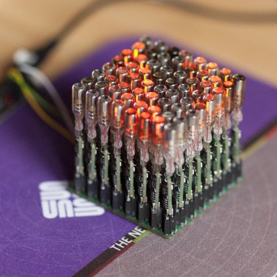
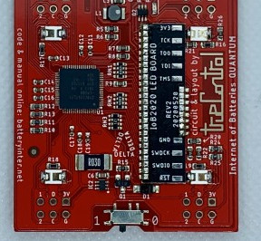
The line of nine RGB LEDs have black bezels which goes along with the black stripe motif and underscores the typography of the badge name. These lights are hosted on a daughter board soldered to the underside of the badge with a slot for the LEDs to pass through. They are addressed in a 2×15 matrix that is scanned on the low side by the PSoC5 that drives the badge. This low-res image shows that daughter board before the lithium cell is placed.