There are a lot of blinky glowy things at Burning Man every year, and [Mark] decided he would literally throw his hat into the ring. He built a high visibility top hat studded with more RGB LEDs than common sense would dictate. It’s a flashy hat, and a very good example of the fashion statement a few hundred LEDs can make.
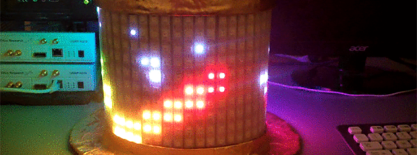
[Mark]’s top hat has 481 WS2812b addressable LEDs studded around the perimeter, a common LED choice for bright and blinky wearables. These LEDs are driven by a Teensy 3.1, with a Bluetooth transceiver, a GPS module, a compass, and gyro/accelerometer attached to the microcontroller. That’s a lot of hardware, but it gives [Mark] the capability of having the hat react to its own orientation, point itself North, and allow for control via a modified Nintendo NES controller.
The WS2812 LEDs draw a lot of power, and for any wearable project having portable power is a chief concern. [Mark]’s original plan was to use an 8x battery holder for the electronics enclosure, and use five AA batteries to power the hat. The total idle draw of the LEDs was 4.5 Watts, and with even a few LEDs blinking colors there was a significant voltage drop. The idea of powering the hat with AA batteries was discarded and the power source was changed to a 195 Watt-hour lithium ion battery bank that was topped off each day with a solar panel.
The hat is awesome, exceedingly bright, and something that gets a lot of attention everywhere it goes. For indoor use, it might be too bright, but this could be fixed with the addition of a bit of black stretchy fabric, like what our own [Mike Szczys] did for his DEF CON hat. [Mark]’s hat is just version 1, and he plans on making a second LED hat for next year.
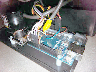 Behind the clock is an Arduino driving a MAX7219 LED controller. Using the MAX7219 was a challenge because it expects a grid of LEDs while the clock needs a linear array. [Dylan] used a line of individual LEDs wired to match what the controller wanted. A rotary encoder tells the processor the position of the arm so the Arduino sketch can determine which LEDs should be lit to show the time and clock face.