As you might expect, the release of last year’s Ghostbusters: Afterlife has not only lead to renewed interest in the old 1980s toys and tie-in merchandise, but has spawned a whole new generation of blinking plastic gadgets to delight children of all ages. Of course, for folks like us, that means more hardware to hack on.
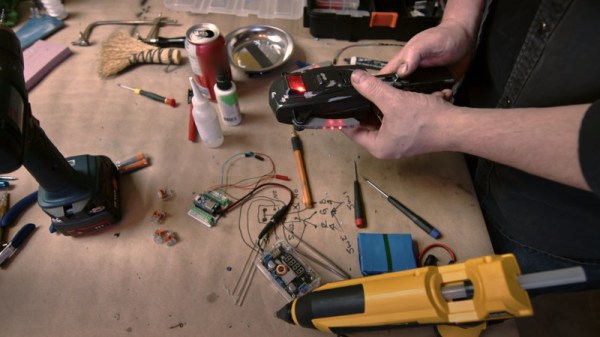
In a recent post to the official Ghostbusters YouTube channel, professional prop maker [Ben Eadie] shows off some of the tricks of the trade when he takes a $15 USD “PKE Meter” toy from Hasbro and turns it into a screen-quality prop. Even if you’re not looking to get an early start on your Halloween costume, the techniques demonstrated in this video could be easily adapted to other projects. For those whose next ideal home improvement is a fireman’s pole and an ectoplasmic laser-confinement grid, you might want to grab a couple of these toys while they’re still cheap for eventual conversion.
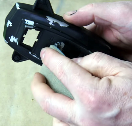
The biggest takeaway from the video is probably the finishing techniques, as they could be used on any sort of realistic prop build. [Ben] starts by using a cabinet scraper to smooth out the lines on the plastic toy, and any holes are filled with the familiar baking soda and cyanoacrylate glue trick. Once the surfaces have been prepped, all the principle parts are sprayed with an adhesion promoter, followed by a coat of silver, and then the final black color.
This allows him to create a convincing “chipped paint” effect by strategically sanding or scraping through the top coat. Dabbing some toothpaste where you want the device to look worn down before spraying the final coat makes the process even faster, as it will prevent the top coat from sticking to the silver in the first place.
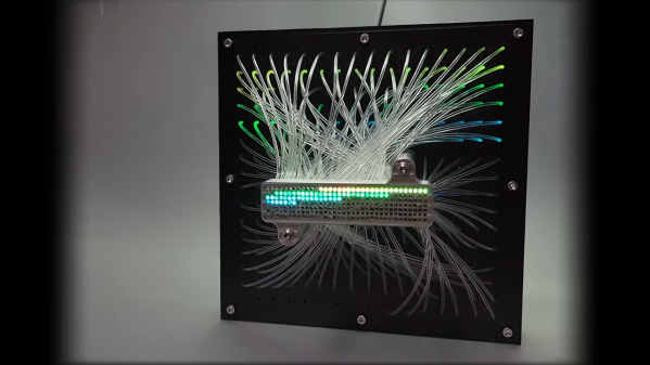
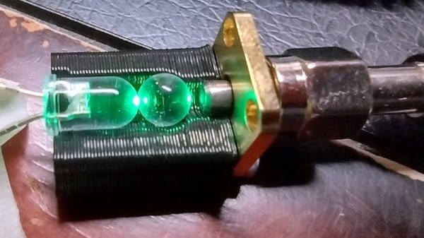
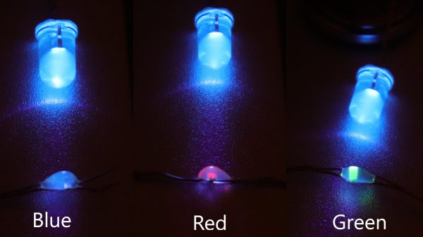
Unfortunately [Ben] doesn’t spend a whole lot of time explaining the electronics side of things, but it doesn’t look like there’s anything too complex going on. All the original gear is stripped, and it gets replaced with a microcontroller which we believe is an Adafruit ItsyBitsy nRF52840 Express. This is connected to two strings of tiny APA102 addressable LEDs which are run down the “wings” (we especially like the 3D printed lenses used to replace the original solid pips), and one that’s used to provide the iconic sine-wave display.
While the last PKE meter build we saw did detect radiation, we have to admit that in terms of looks, this one takes the top spot. Especially when you consider how cheap the thing was. All you need now is a Proton Pack, and you’ll be ready for Halloween.
Continue reading “Cheap Ghostbusters Toy Turned Convincing Prop”