What’s Your Fidget Spinner Say?

The persistence of vision (POV) optical illusion is pretty common in cheap toys nowadays, but how cool would it be to have your own programmable POV message board? German electronics grad student [Matej] has luckily created an open source fidget spinner with a fully customizable POV display that lets you share whatever thoughts you’d like fellow fidget spinning friends to know.

The displayed graphics don’t rely on rotation velocity, thanks to a solution that tracks the rotation angle. Unlike over POV devices, the POV fidget spinner displays the same graphics at higher and lower rotational speeds, which is useful considering the fidget spinner doesn’t automatically spin at the same rotational speed for every user. It also doesn’t require a constant speed for the image to be displayed correctly, unlike POV fans or clocks.

Continue reading “What’s Your Fidget Spinner Say?”

Can You Read Me The Time?

If you’re like the average clock user, you’ve probably gotten annoyed at reading analog clocks before. Typically, the solution is just to use a digital timepiece, but [sjm4306] has opted to make a small word clock that you can carry with you wherever you go to remind you of the time in the English language.

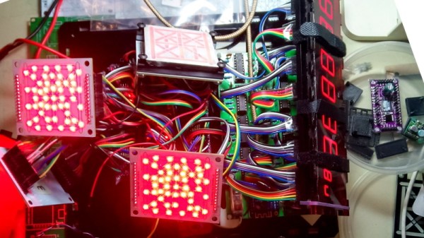
Unlike a similar project made by [Gordan Williams], which uses an 8 x 8 LED matrix with an inkjet printed overlay, this small word clock uses a 3D-printed light box to achieve its letter matrix. In fact, they were inspired by all of the existing DIY word clock designs using anything from off-the-shelf LED arrays, transparency masks and WS2812s.

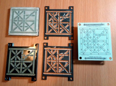
The design uses a home-brewed PCB design that runs off 5 V via USB. The design places the letters on the top stop and restricts layers to keep the solder mask and copper from obstructing the light. The bottom side uses the same design principle with a square shape that overlaps the letter. In order to block light between adjacent letters, the 3D-printed light box comes into play.

One design challenge for the letter matrix was fitting all possible minutes into the array. Rather than making a larger array of letters, [sjm4306] had the clock describe the time down to five-minute intervals then add asterisks for the full time. It’s a pretty understandable solution for keeping the design simple, and the letters all fit onto the design so well!

Using a pin map assigned to the I/O for the rows and columns of the array, the software toggles the states of the pins as a switch statement. For scanning the matrix, the software uses an interrupt that draws the current column of LEDs and updates the display image before incrementing to the next column. By skipping or not skipping cycles, this allows the display to look brighter or dimmer.

The time tracking is fairly simple, using a DS1302 serial real time clock chip – it even charges a super capacitor to keep time after power is removed!

To tackle the light scattered internally in the PCB’s FR4 material, a separator is used to contain the light. As a low-cost solution, while there is still some amount of light diffused, it’s definitely better than without the separator.

Almost all of the files used for building the small word clock are available on [sjm4306]’s project page, including the software and design files. It hopefully won’t be too long before we start seeing more of these low-cost word clock designs!

Continue reading “Can You Read Me The Time?”

RGB Lamp With Micro:Bit Powered Gesture Control

The Micro:bit is a very neat piece of hardware that, frankly, we don’t see enough of. Which made us all the more interested when [Manoj Nathwani] wrote in to tell us about the gorgeous 3D printed RGB LED lamp he created that uses the BBC-endorsed microcontroller to perform basic gesture detection. Purists will likely point out that an Arduino Pro Mini is tagging along to handle interfacing with the LEDs, but it’s still a good example of how quick you can get a project up and running with MicroPython on the Micro:bit.

[Manoj] used eight NeoPixel Sticks, a NeoPixel Ring, and a few scraps of perfboard to construct a three dimensional “bulb” to fill the void inside the printed diffuser. They’re chained together so all the elements appear as a single addressable strip, which made the rest of the project a bit easier to implement. It might not be pretty, but it gets the job done and it’s not like you’ll ever see it again once installed in the lamp anyway.

The Micro:bit and Arduino co-pilot live in the base of the lamp, and the single USB cable to provide power (and the ability to update the device’s firmware) is run out the bottom to give the whole thing a clean and professional look. For those wondering why the Arduino has tagged along, [Manoj] says he couldn’t get the NeoPixel libraries to play nicely with the Micro:bit so he’s using the Arduino essentially as a mediator.

Right now the only gesture that’s detected on the Micro:bit is a simple shake, which tells the Arduino to toggle the light show on and off. But in the future, [Manoj] plans to implement more complex gestures which will trigger different animations. As he explains in the blog post, gesture recognition with the Micro:bit is incredibly simple, so it should be easy to come up with a bunch of unique ways to interface with the lamp.

Color changing LED lamps are a favorite project of hackers, and we’ve seen examples built with everything from glass and copper to laser-cut pieces of wood and veneer. While you might prefer to skip the gesture control for an ESP8266 and UDP, we think this project is another strong entry into this popular genre.

Glitching LED Display Proves Crowd Favorite

There’s something enchanting about the soft glow of a properly diffused LED, and this is only improved by greater numbers of LEDs. [Manoj Nathwani] was well aware of this, setting out to build a large display using ping-pong balls for their desirable optical qualities.Unfortunately, not everything went to plan, but sometimes that’s not all bad.

The matrix, built back in 2016 for EMF Camp, was sized at 32×18 elements, for a total of 576 pixels. This was achieved with the use of 12 WS2811 LED strips, with the lights set out on a 50mm grid. Cheap knock-off pingpong balls were used for their low cost, and they proved to be excellent diffusers for the LEDs.

With everything wired up to a NodeMCU, basic testing showed the system to be functioning well. However, once the full matrix was assembled in the field, things started to fall over. Basic commands would work for the first 200 LEDs or so, and then the entire matrix would begin to glitch out and display random colors. Unable to fix the problem in the field, [Manoj] elected to simply run the display as-is. Despite the problems, passers-by found the random animations to be rather beautiful anyway, particularly at night.

After the event, [Manoj] determined the issue was due to the excessive length of the data line, which in the final build was 48 meters long. While the problem may be rectified when [Manoj] revisits the project, the audience seemed to appreciate the first revision anyway.

LED displays will be a hacker staple until the heat death of the universe. Ping pong balls will also likely retain their position as a favorite diffuser. If you’ve got a great LED build of your very own, be sure to hit up the tips line!

Stack Those Boards For An Extra-Special Backlit LED Effect

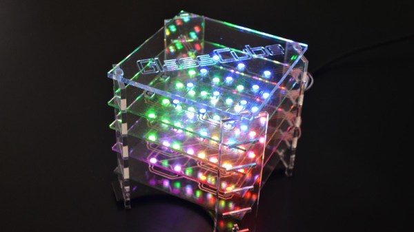
By now most of us should be used to backlit LEDs, in which a bare board with no copper or soldermask as an LED mounted on its reverse side to shine through as if with a diffuser. [Wim Van Gool] has created such an LED display with a twist, instead of reverse mounted LEDs his Shitty Add-On for Area3001 hackerspace in Leuven, Belgium has a set of WS2812 addressable LEDs shining upwards through a void in a stack of PCBs to the diffuser. The effect is of something that looks about the size and shape of a Kit-Kat finger with a glowing hackerspace logo on the front, and it breaks away from the SAO norm.

Full details are on the GitHub repository for the project, in which we find both large and small takes on the same idea. It appears that there is no onboard processor and that the WS2812s are driven from the host badge, but that doesn’t take away from the ingenuity of the design.

The through-PCB diffuser seems to be the badge must-have of the moment, we’ve seen quite a few such as the recent Numberwang badge. That’s the exciting thing about badge design though, one always knows that there will be a new twist along in the next crop of badges, to keep everything fresh.

Tiny LED Cube Packs Six Meters Of Madness

When [Freddie] was faced with the challenge of building a sendoff gift for an an LED-loving coworker he hatched a plan. Instead of making a display from existing video wall LED panels he would make a cube. But not just any cube, a miniature desk sized one that wasn’t short of features or performance. We’d be over the moon if someone gifted us with this itty-bitty Qi coil-powered masterpiece of an RGB cube.

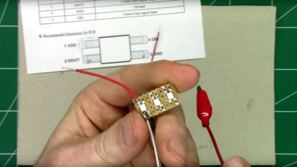
Recently we’ve been blessed with a bevy of beautiful, animated RGB cubes but none hit quite this intersection of size and function. The key ingredient here is tiny but affordable RGB LEDs which measure 1 mm on a side. But LEDs this small are dwarfed by the otherwise minuscule “2020” package WS2812’s and APA102s of the world. Pushing his layout capabilities to the max [Freddie] squeezed each package together into a grid with elements separated by less than 1 mm, resulting in a 64 LED panel that is only 16 mm x 16 mm panel (with test points and controller mounted to the back). Each of these four-layer PCBs that makes up the completed cube contains an astonishing 950 mm of tracking, meaning the entire cube has nearly six meters of traces!

How do you power such a small device with no obvious places to locate a connector? By running magnet wire through a corner and down to a Qi coil of course. Not to let the cube itself outshine the power supply [Freddie] managed to deadbug a suitably impressive supply on the back of the coil itself. Notice the grain of rice in the photo to the left! The only downside here is that the processor – which hangs diagonally in the cube on a tiny motherboard – cannot be reprogrammed. Hopefully future versions will run programming lines out as well.

Check out the video of the cube in action after the break, and the linked photo album for much higher resolution macro photos of the build. While you’re there take a moment to admire the layout sample from one of the panels! If this sets the tone, we’re hoping to see more of [Freddie]’s going-away hacks in the future!

Continue reading “Tiny LED Cube Packs Six Meters Of Madness”

Big And Glowy Tetris Via Arduino

TetrisĀ was a breakout hit when it was released for the Nintendo Game Boy in 1989, in much the same way thatĀ Breakout was a breakout hit in arcades in 1976. Despite this, gamers of today expect a little more than a tiny monochrome LCD with severe motion blur problems. Enter the LED Tetris build from [Electronoobs].

The build relies on a hacker favourite, the WS2812B LED string. The LEDs are set up in a 8×16 matrix to create the familiar Tetris playfield. Buttons and a joystick are then installed on the front panel to allow the player to control the action. An Arduino Mega runs the show, with a DFPlayer used to play the famous theme music as the cherry on top.

It’s a fun build that would be an awesome addition to any hacker’s coffee table. Big glowing LEDs make everything better, after all – this ping-pong ball display is a great example of the form. Video after the break.

Continue reading “Big And Glowy Tetris Via Arduino”