Composing music can be quite difficult – after all, you have to keep in mind all of the elements of musical theory, from time signature and key signature to the correct length for all of the notes. A team of students from Cornell University’s Designing with Microcontrollers class developed a solution for this problem by transcribing sounds from a flute into sheet music.
The project doesn’t simply detect the notes played – it is able to convert the raw audio into a standardized music score complete with accurate note timings and beats per minute. Before transcribing the music, some audio processing was necessary. The team chose to use a Sallen-Key filter to amplify the raw audio input due to its complex conjugate poles. They then used a fast Fourier Transform (FFT) to determine the frequency for the input note, converting the signal from the time domain to the frequency domain.
The algorithm samples the data to generate an input signal, using the ADC on the microcontroller to receive input from the microphone. It takes the real and imaginary components of the sampled signals and outputs a pair of real and imaginary amplitude components corresponding to the sampled frequency, evenly spaced from 0 to the Nyquist rate (half the sampling rate). The spacing of these bins and the bin with the largest amplitude are used to convert the signal back to a real frequency and a MIDI note.
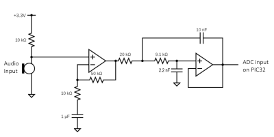
The system uses a PIC32 for the logic. The circuitry for the microphone amplification uses a non-inverting op-amp with a gain of 50 to increase the microphone output signal amplitude from 15 mV to 750 mV to use by the microcontroller’s ADC. The signal is then sent to the anti-aliasing Sallen-Key filter, with a pole at 2.5 kHz and a Q of 1. The frequency was chosen since the FFT samples at 8 kHz and the frequency corresponds to a note out of the range of a flute. As for the filters, only the low pass filter was implemented in hardware. While a bandpass filter could have been implemented in hardware, the team decided on a cleaner software approach.
The project is well-documented on the team’s project page, and it’s certainly worth checking out for more detailed discussions on the keypad controls and the software side of the audio processing. If you want to learn more about the FFT, check out this 2016 Hackaday Prize entry for an FFT spectrum analyezer.
Continue reading “Turning Sounds From A Flute Into Sheet Music”