Tweeting From The NES Expansion Port

[Trapper] is an 80’s kid, and back in the day the Nintendo Entertainment System was his jam. One fateful night, he turned over his favorite gray box, removed a small plastic guard, and revealed the mythical expansion port. What was it for? What would Nintendo do with it?

The expansion port on the NES wasn’t really used for anything, at least in the US market. Even in the homebrew scene, there’s only one stalled project that allows the NES to connect to external devices. To fulfill [Trap]’s childhood dream, he would have to build something for the NES expansion port. Twitter seemed like a good application.

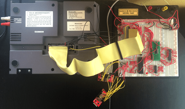
The first step towards creating an NES Expansion Port Twitter thing was to probe the depths of this connector. The entire data bus for the CPU is there, along with some cartridge pass-through pins and a single address line. The design of the system uses a microcontroller and a small bit of shared SRAM with the NES. This SRAM shares messages between the microcontroller and NES, telling the uC to Tweet something, or telling the NES to put something on the screen.

Only a single address pin – A15 – is available on the expansion port, but [Trapper] needed to read and write to a certain section of memory starting at $6000. This meant Addresses A13 and A14 needed to be accessed as well. Fortunately, these pins are available on the cartridge slot, and there are a number of cartridge pass-through pins on the expansion connector. Making a bridge between a few pins of an unused cartridge solved this problem.

From there, it’s just a series of message passing between a microcontroller and the NES. With the help of [Trap]’s brother [Jered] and a Twitter relay app running on a server, this NES can actually Tweet. You can see a video of that below.
Continue reading “Tweeting From The NES Expansion Port” →

A Deadbugged GPS/GLONASS/Geiger Counter

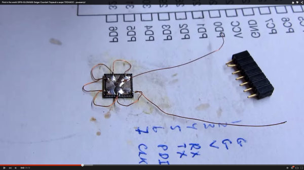
So you think you’re pretty good at soldering really tiny parts onto a PCB? You’re probably not as good as [Shibata] who made a GPS/GLONASS and Geiger counter mashup deadbug-style with tiny 0402-sized parts.

The device uses an extremely small GPS/GLONASS receiver, an AVR ATxmega128D3 microcontroller, a standard Nokia phone display and an interesting Geiger tube with a mica window to track its location and the current level of radiation. The idea behind this project isn’t really that remarkable; the astonishing thing is the way this project is put together. It’s held together with either skill or prayer, with tiny bits of magnet wire replacing what would normally be PCB traces, and individual components making up the entire circuit.

While there isn’t much detail on what’s actually going on in this mess of solder, hot glue, and wire, the circuit is certainly interesting. Somehow, [Shibata] is generating the high voltage for the Geiger tube and has come up with a really great way of displaying all the relevant information on the display. It’s a great project that approaches masterpiece territory with some crazy soldering skills.

Thanks [Danny] for sending this one in.

Continue reading “A Deadbugged GPS/GLONASS/Geiger Counter” →

The Digistump Oak; An ESP8266 On Kickstarter

When it was first released, the ESP8266 was a marvel; a complete WiFi solution for any project that cost about $5. A few weeks later, and people were hard at work putting code on the tiny little microcontroller in the ESP8266 and it was clear that this module would be the future of WiFi-enabled Things for the Internet.

Now it’s a Kickstarter Project. It’s called the Digistump Oak, and it’s exactly what anyone following the ESP8266 development scene would expect: WiFi, a few GPIOs, and cheap – just $13 for a shipped, fully functional dev board.

The guy behind the Oak, [Erik Kettenburg], has seen a lot of success with his crowdfunded dev boards. He created the Digispark, a tiny, USB-enabled development board that’s hardly larger than a USB plug itself. The Digispark Pro followed, getting even more extremely small AVR dev boards out in the wild.

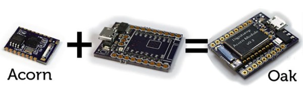
The Digistump Oak moves away from the AVR platform and puts everything on an ESP8266. Actually, this isn’t exactly the ESP8266 you can buy from hundreds of unnamed Chinese retailers; while it still uses the ESP8266 chip, there’s a larger SPI Flash, and the Oak is FCC certified.

Yes, if you’re thinking about building a product with the ESP8266, you’ll want to watch [Erik]’s campaign closely. He’s doing the legwork to repackage the ESP into something the FCC can certify. Until someone else does it, it’s a license to print money.

The FCC-certified ESP8266 derived module, cleverly called the Acorn, will be available in large quantities, packaged in JEDEC trays sometime after the campaign is finished. It’s an interesting board, and we’re sure more than one teardown of the Acorn will hit YouTube when these things start shipping.

Brewdoo Helps Keep The Office Coffee Fresh

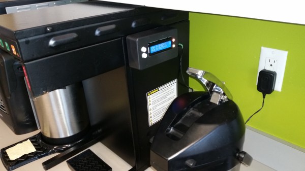
Until about lunch time, the coffee goes pretty fast in our office. Only a few of us drink it well into the afternoon, though, and it’s anyone’s guess how long the coffee’s been sitting around when we need a 4:00 pick-me-up. It would be great to install a coffee timer like [Paul]’s Brewdoo to keep track of these things.

The Brewdoo’s clean and simple design makes it easy for anyone in the office to use. [Paul]’s office has two carafes, so there’s a button, an RGB LED, and a line on the LCD for each. Once a pot is brewed, push the corresponding button and the timer is reset. The RGB LED starts at green, but turns yellow and eventually red over the course of an hour. Brewdoo has a failsafe in place, too: if a timer hasn’t been reset for four hours, its LED turns off and the LCD shows a question mark.

[Paul] knew he couldn’t touch the existing system since his company leases the equipment, so the Brewdoo lives in an enclosure that [Paul] CNC’d with custom g-code and affixed to the brewing machine with hard drive magnets. Although [Paul] designed it with an Arduino Uno for easy testing and code modification, the Brewdoo has a custom PCB with a ‘328P. The code, Fritzing diagram and Eagle files are up at [Paul]’s GitHub.

Simple Keypad Scanning With SPI And Some Hardware

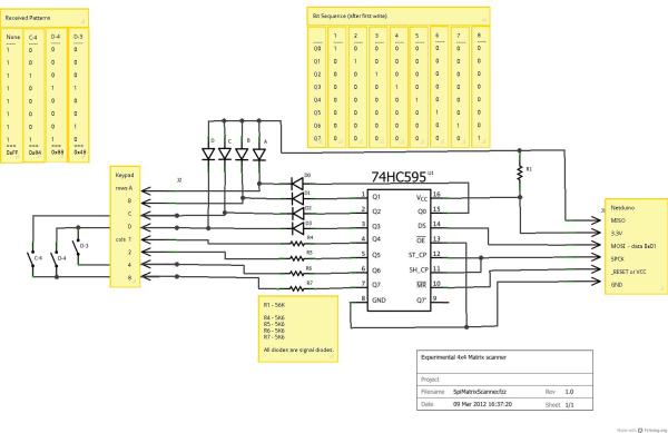
16-button keypads have a clever method of encoding their data into 8 pins. Pins are mapped to four rows and four columns on the keypad. A user reads the keypad by bringing each row up to logic: HIGH, and reading the corresponding column values, (HIGH or LOW). Keypad scanning can be farmed out to a microcontroller with a simple finite-state machine and some button debouncing techniques. [Mario], [Glen], and [Paul] on the Netduino forums took an entirely different route: they’ve designed and implemented a Keypad Scanner using any microcontrollers SPI peripheral and a 74HC595 Shift register.

The trio’s solution is an elegant adventure into circuit design. With two diodes and a voltage divider, they devise a simple circuit that pulls the SPI MISO line LOW if a button in the corresponding circuit’s row is pushed closed. Copied four-fold, this circuit joins the rows and columns of the 74HC595 to the keypad matrix. To scan across the four columns, the microcontroller performs an SPI transfer of the key value: 0x01. To decode which button is pushed, the value received back from the SPI bus encodes which button was pushed out of the 16 possible buttons. Note: some cases for ambiguity as to “which button was pressed” do exist if multiple buttons are pushed at the same time, but for the general case where we’re punching in values one-by-one, this circuit works perfectly.

The team’s hack is a clever use of existing hardware to outsource a microcontroller’s software problem to hardware while leveraging the SPI peripheral to cleverly decrypt and retrieve data back from the keypad. Kudos to the team of three over at the Netduino Forums, and we’re always thrilled to see and idea grow from one person to the next. In case you want to take a step lower and build up the keypad itself, here’s a blast from the past that does just that.

Showing An AVR Programmer Who’s Boss

[Bogdan] makes a good point. When you use a dev board you get programming, debugging, power sourcing, and usually a UART. When you go to the trouble of hooking up a programmer why don’t you get the same thing? Astutely, he points out that all you usually get with programmers is programming. So he set out to add features to the hardware he uses to program XMEGA.

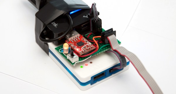
The first part of the trick hinges on his use of PDI programming. This is slightly different from ISP programming. Both use a six-pin connector cable but with PDI two of these pins are unused. He took this opportunity to reroute the chip’s TX and RX pins through the cable, which now gives him an avenue to use a UART-to-USB adapter without adding any cables to his target board. Rather than add a second USB cable he rolled a USB hub into the mix. An LM1117 regulates the 5V USB rail down to 3.3V as a source for the target board.

The programmer being used is an Atmel ICE. As you might imagine he didn’t want to make permanent alterations to it. His modifications are all handled externally, with one IDC cable connecting the programmer to his added circuitry and another headed off to the target board. For now he’s jumpering RX/TX to the programming header but plans to route the signals on future PCBs.

Even More Emulated Microcomputers: 8080 On A Stellaris Launchpad

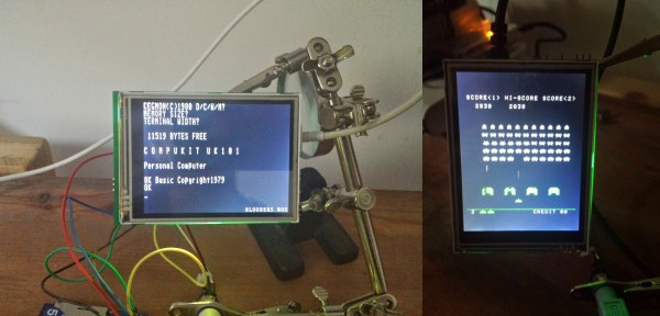
[Steeeve] just sent us his work on emulating a handful of 8080-based microcomputers on a Stellaris Launchpad, including the bare-metal to run Space Invaders. We know what you’re thinking: Is that all you folks are doing these days?!?!? There must be something in the water.

[Steeeve]’s build is based on the Launchpad with an external 64kB of SPI RAM, a nice little TFT display, and a built-in SD card for all of your storage needs. Add in an 8080 emulator and a keyboard and you’ve got a tiny microcomputer. (Is that redundant?)

What’s really neat about [Steeeve]’s project is that he’s cloned not just one target computer, but a whole bunch of computers including (GitHub links follow) the 8080-based UK101/Superboard, the CPM/80, and the machine that ran Space Invaders, as well as the 6502-based Commodore PET and Apple-1.  And as a bonus, you can save the state onto the built-in SD card so that you can hibernate the microcomputer and pick up right back where you left off at a later date. Snazzy.

He’s also built a library which provides an emulation framework if you want to build on this work yourself. And did we mention he can play Space Invaders? Bravo [Steeeve]!