The 128 Button, 6 Axis, 17 Slider, 4 POV Hat Switch Joystick Controller

stick

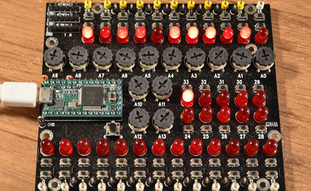
[Paul Stoffregen], creator of the Teensy series of dev boards, previously implemented a six-axis joystick for Teensyduino, the Arduino library for the Teensy. He had originally tried 8 axes, but a few problems cropped up, deadlines approached, and he left it as is. A few recent projects gave him some insight into how to implement a joystick with more than six axes as a USB HID device, so he started looking at how to read an improbable amount of pots and buttons for a USB joystick.

So far, the biggest problem is figuring out what software can actually use an HID joystick with this many controls. The answer to that question is none. The Linux-based jstest-gtk is able to read 6+17 pots, the four hat switches, but only 64 of the 128 buttons. A user on the Teensy forums, [Pointy], has been working on his own joystick test app that works on Linux Windows, but testing the joystick on Windows is an exercise in futility for reasons no one can figure out.

As for why anyone would want a six-axis, 17-slider, 128-button joystick, think about this: with this much control, it would be relatively simple to build the MIDI controller to end all MIDI controllers, or a cockpit simulator for everything from a C172, 737, to a Kerbal interplanetary cruiser. That’s an impressive amount of control, and all from a $20 Teensy dev board.

Further testing of this Teensy joystick is desperately needed, so if you’re able to help out drop a note in the forum thread.

Motion Tracking On The Cheap With A PIC

motion tracking

Ever need a cheap motion tracker for very basic object following? Did you know you can throw one together with a few IR distance sensors and a PIC?

The setup is fairly simple. [Aron Horan] is using a dsPIC30F4011 PIC, a SHARP infrared distance sensor, an RC servo, and a PICkit2 for testing. It works by scanning left and right using the servo motor. When the edge of an object is detected, it will turn away from the object until it can no longer detect the edge — then it turns back. Unfortunately this does mean it will always be twitching, even when it’s tracking an object.

Like many of the other projects [Aron] has documented, he’s included everything you need to know to be able to recreate the project yourself. Flowcharts, wiring diagrams, and the code — written in C of course! The following video includes an excellent demonstration, but if you want to skip straight to the action, you can see it start tracking a multimeter at about 0:39 in.

Continue reading “Motion Tracking On The Cheap With A PIC”

Java Grinder Spits Out DsPIC And MSP430 Assembly Code

java-code-grinder

[Michael Kohn] sent in a link to the set of projects he’s been working on lately. The Java Grinder is a project that converts Java code for use on microcontrollers. This actually started back in 2009, when he mentioned that the project was worthless because there were already a ton of Java virtual machines out there. But if he had really thought that he’d never learn anything. We’re glad [Michael] picked this back up and made something out of it.

The image above shows the proof of concept. It’s a box bouncing around the Nokia 6100 screen. He wrote the animation in Java, and used his grinder to turn the code into dsPIC assembly, which was then compiled and flashed onto the microcontroller. That’s not all, he’s also coded a Mandelbrot set generator or the same hardware. As it stands he can also produce assembly code for use on MSP430 chips.

This kind of exploration is great for the brain. We see it as a natural extension of the learning you acquire from Nand2Tetris which walks through the essential text The Elements of Computing Systems. If you’re not familiar, that’s a trip from building your first logic gate, which you plunk together with others to build an ALU, then start coding all the way up to a virtual machine to run on your simulated hardware.

Video of the bouncing box and Mandelbrot set is below.

Continue reading “Java Grinder Spits Out DsPIC And MSP430 Assembly Code”

Single Digit Numitron Clock

numitronClock

The above may look like a Nixie tube, but it’s a Numitron: the Nixie’s lower-voltage friend, and part of [pinomelean’s] single-digit Numitron clock. If you’re unfamiliar with Numitrons, we suggest you take a look at our post from a few years ago, which includes a helpful tutorial to catch you up to speed.

[pinomelean] built this little device to capture a steampunk-ish look on the cheap for a clock small enough to fit on a wrist. The build uses a PIC16F84A uC and a 4MHz crystal on a custom PCB. A small button on the side lets the wearer set the time. Similar to the Vibrating Timepiece from last month, the Numitron clock isn’t perfect, though it is more accurate: gaining only one minute every 3 days.

Check out the video after the break to see it being set and keeping track of the time. It may take a moment to understand how to read the clock, though. Each of the four LEDs indicates where the number in the Numitron tube belongs. The LEDs light in sequence from left to right, displaying the clock one digit at a time.

Continue reading “Single Digit Numitron Clock”

Mario Doorbell Guaranteed To Drive A-You A-Crazy

marioDoorbell

Is your doorbell not exciting enough for your guests? [Joe] wanted to provide a little entertainment for his visitors, so he redesigned his doorbell with a Mario theme.

Whenever someone presses the button—which carries the Mario coin image—the segment display increments and the Mario coin sound plays. To add variety, the life-up sound plays at every 10 coins and the mushroom upgrade sound plays upon reaching 100. [Joe] tried putting the life-up sound at its appropriate 100’s place and the mushroom sound at every 10, but he decided the brevity of life-up was more tolerable in the 10’s slot.

The project was divided into two components. The door button has a PIC16F628A microcontroller with a dual 7-segment LED display, a button, and a homemade circuit board. All this lives in a simple box covered by a Yoshi’s Island-themed decal. The button’s board connects to a separate ringer board—based around a PIC16F87—with a MCP4822 DAC and a 25LC1024 EEPROM. Button presses on the first board prompt a request for a sound clip read on the EEPROM. Keep clicking for a demo video below.

Continue reading “Mario Doorbell Guaranteed To Drive A-You A-Crazy”

Tic Tac PIC Pack: A Pocket Programmer

Sure, mint tin housings are great. But you have to defend against shorts, and cutting out holes for ports and buttons is dangerous business. [Daniel] prefers plastic, and he tipped us off about a PICKit2 clone that he designed to fit inside of a tic tac box.

Almost all of the components were salvaged except for the microcontroller and the connectors. He wound his own inductor using the ferrite core from a CFL. [Daniel] had to make a few improvisations for this project. He didn’t have a 20MHz crystal, so he used a 12MHz crystal and tweaked the fuse bits after burning the firmware.

To save space on the board, he soldered wires to RESET, VCC, GND, PGD, and PGC to program the firmware and then removed the wires. The only trouble he had with it was more or less easily solved by replacing two transistors.

You may remember that we linked to his USBasp programmer in a mentos container a few months back. We figure [Daniel] must have some pretty fresh breath.

WS2811 SPI Driver Using One Transistor And Passives

ws2811-spi-driver

We love the WS28xx projects because even if we never plan to use them, the signal timing is like the most addictive puzzle game ever. For instance, check out this WS2811A driver which uses hardware SPI to generate the signals.

The WS28xx offerings place a microcontroller inside an RGB LED, allowing them to be individually addressed in very long chains or large matrices (still a chain but different layout). But the timing scheme used to address them doesn’t play well with traditionally available microcontroller peripherals. [Brett] had been intrigued by some of the attempts to bend hardware SPI to the will of the WS2811 — notably [Cunning_Fellow’s] work featured in this post. He took it a great step forward by simplifying the driver to just one transistor, three resistors, and a capacitor.

Click through the link above for his step-by-step description of how the circuit works (it’s not worth re-explaining here as he does a very concise job himself). The oscilloscope above shows the SPI signal on top and the resulting timing signal below. You will notice the edges aren’t very clean, which requires the first pixel to be very close to the driver or risk further degradation. But, since the WS28xx drivers feature a repeater which cleans up signals like this, it’s smooth sailing after the first pixel.