There’s no shortage of devices out there for creating electronic music, but if you’re just looking to get started, the prices on things like synthesizers and drum machines could be enough to give you second thoughts on the whole idea. But if you’ve got a well stocked parts bin, there’s a good chance you’ve already got most of what you need to build your own Crunch-E.
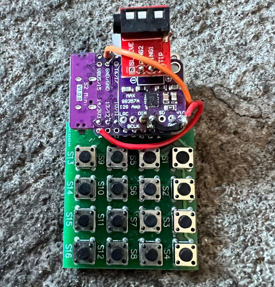
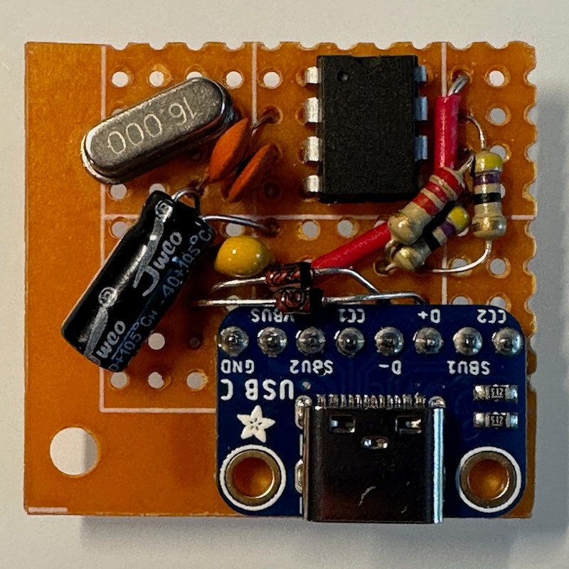
Described by creator [Roman Revzin] as a “keychain form factor music-making platform”, the Crunch-E combines an ESP32, an MAX98357 I2S audio amplifier, an array of tactile buttons, and a sprinkling of LEDs and passives. It can be built on a perfboard using off-the-shelf modules, or you can spin up a PCB if you want something a bit more professional. It sounds like there’s eventually going to be an option to purchase a pre-built Crunch-E at some point as well.
But ultimately, the hardware seems to be somewhat freeform — the implementation isn’t so important as long as you’ve got the major components and can get the provided software running on it.
The software, which [Roman] is calling CrunchOS, currently provides four tracks, ten synth instruments, and two drum machine banks. Everything can be accessed from a 4 x 4 button array, and there’s a “cheat sheet” in the documentation that shows what each key does in the default configuration. Judging by the demo video below, it’s already an impressively capable platform. But this is just the beginning. If everything goes according to plan and more folks start jamming on their own Crunch-E hardware, it’s not hard to imagine how the software side can be expanded and adapted over time.
Over the years we’ve seen plenty of homebrew projects for producing electronic music, but the low-cost, simple construction, and instant gratification nature of the Crunch-E strikes us as a particularly compelling combination. We’re eager to see where things develop from here.
Continue reading “ESP32 Powered Crunch-E Makes Beats On The Go”