Regarding Atmel’s Xmega Chips

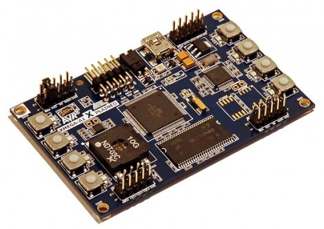
A few years back Atmel announced a new line of chips, the XMega series. We see the name bouncing around here and there, but when [Michael Kleinigger] mentioned that he’s seen very few project using these chips we realized that not only is he right, but we know next to nothing about them. Just give his XMega review post a whirl and you’ll be up to speed in no time.

He compares an XMega128A1 side-by-side with an ATmega1280. For those that abhor reading paragraphs full of words, there’s a table that can give you the quick facts like how the XMega costs less and runs faster. But we know from past discussions (like the one on PWM) that [Mike] knows his stuff so the whole thing’s worth a read. He’ll lead you through the programming tool chain (which hasn’t changed), a bit about the new event system, and then finish with a demo program on the Xplained development board.
All About Accelerometers

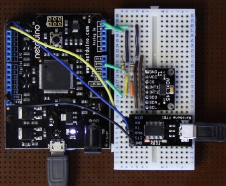
If you’ve ever wondered about the use of or theory behind or the use of accelerometers, this tutorial by Love Electronics is a very good resource. In this article, Love takes one through how to hook up an ADXL345 accelerometer and use it with a Netduino processor. Before the subject of hooking everything up is broached, a very good discussion is given on the general theory and operation of accelerometers.

Information is given about installing all the required software and libraries. Additionally, a mini tutorial about writing a “hello” application using the .NET framework is given. Finally, the application gives the [Windows Presentation Foundation] tools necessary to visualize the raw data that the Netduino produces.

One could really start using this processor and accelerometer from scratch with this tutorial and some basic electronics knowledge.  This could add a great new feature to your next robot or allow measurement that couldn’t be done with simpler sensors.

The Firebird32, A New Dev Board On The Block

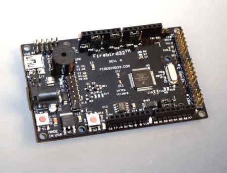
Here is yet another development board to add to your list (If you are into keeping lists), introducing the Firebird32. There seems to be no end to the production of new development boards, following the current style the Firebird32 comes in the familiar Arduino form factor to fit all of your Arduino shields.

The Firebird32 from [Wytec] is build around the 32bit Freescale Flexis MCU [MCF51JM128] running the Coldfire V1 core commonly found in industrial and medical equipment. We were kindly donated a board before release, the first thing that we noticed was  the onboard 8×2 segment LCD which makes the perfect debuging tool. The board along with fitting standard Arduino shields has extra input headers for a keypad, an accelerometer and an extra communication header (IC2/SPI/SCI). It’s also sporting 8 x 12bit analogue inputs, external 32k EEPROM, an RGB LED, a buzzer and an extra push button. The Flexis chip along with the beefy 32bit processor can run at a clock rate up to 48Mhz using PLL and has an integrated USB port, all of this for under $30.

Continue reading “The Firebird32, A New Dev Board On The Block” →

Using Binary Code Modulation To Control LED Brightness

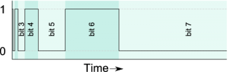
Pulse Width Modulation is definitely the preferred method of dimming an LED with a microcontroller, but we were interested in hearing about a different method called Binary Code Modulation. BCM does the same thing as PWM, it turns the LED on and off very rapidly so that your eye cannot detect a flicker. The brightness level is a result of the average amount of time the LED is on versus when it is off. This is called duty cycle and although it can be the same percentage for both PWM and BCD, there is a fundamental difference.

While PWM usually uses a cyclical on/off cycle (30% on, 70% off, repeat) BCD uses a cumulative cycle. As you can see above, each successive bit of binary code carries double significance compared to the previous bit. Now just assign a duty cycle based on your precision, and have an interrupt fire for each bit of the counter. The graph above shows some highs and some lows combining to reach the target duty cycle. An interrupt is used for each bit, and pin changes are made in the service routine.

The benefit of this system is that it is scaleable without adding overhead. You’re already running the interrupts so servicing 8 or 128 LEDs doesn’t have vastly different needs as it would with PWM. The big downside is that the more bits of precision you use, the faster your processor must run so that the eye doesn’t detect the lengthy on or off cycles of the higher bits as visible flickering.

Thank you [Yetihehe] for tipping us off about a link that [Tomas Martinsen] left when commenting about an Arduino library for up to 768 PWM outputs.

FPGA Arduino Shield Uses Kickstarter As A Preorder System

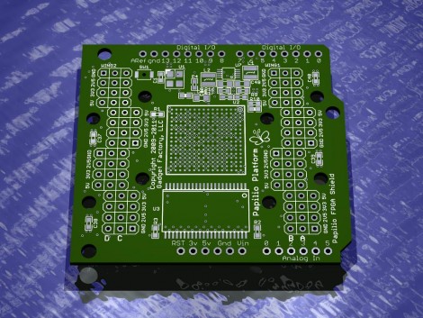
[ Jack Gassett] is working on an FPGA shield for the Arduino. At first the idea of this expansion board seemed a little silly. But [Jack] mentions that the FPGA board can be quite useful for adding higher-order electronic complexity like HDMI capabilities to an Arduino. We’re not totally sold on the idea, but he’s not making the board solely for use with an Arduino either.

The plan is to use a Xilinx Spartan 3A FPGA which comes in a ball-grid array package. And that is the reason [Jack] decided to use Kickstarter for this project. He shared some of his issues with BGA components in a home manufacturing process a while back. To get these working reliably you need to have them professionally assembled, and that requires a sizable upfront investment. But as we read through his proposal it struck us that he’s actually using Kickstarter as a preorder system. You can get a base model with just the FPGA soldered on the board for $55. Not bad considering the chip will cost you at least $20 without assembly. Each level up includes a few more components like SRAM or add-on PCBs.

We get a lot of tips pointing to Kickstarter proposals but this is one of the few that seems right on the mark for supporting open and innovative development. Great work [Jack]!

[Thanks Simon]

DIY Wiper Speed Control And Collision Avoidance

ir_sensor_rain_detection

On many new cars, automatic wiper speed control can be had as an upgrade, though most cars do not offer front-end collision prevention at all. [Rishi Hora] and [Diwakar Labh], students at the Guru Tegh Bahadur Institute of Technology in New Delhi, developed their own version of these features, (PDF warning, skip to page 20) which they entered into last year’s Texas Instruments Analog Design Contest. Under the guidance of professors [Gurmeet Singh] and [Pawan Kumar], the pair built the systems using easily obtainable parts, including of course, an MSP430 microcontroller from TI.

The collision prevention system uses a laser emitter and an optical detector to estimate the distance between your car and the vehicle in front of you, sounding an alarm if you are getting too close. In a somewhat similar fashion, the wiper speed control system uses an IR emitter and detector pair to estimate the amount of water built up on the windshield, triggering the wipers when necessary.

While not groundbreaking, the systems would be quite handy during monsoon season in India, and seem easy enough to install in an older vehicle. The only thing we’re not so sure about is pointing lasers at cars in traffic, but there are quite a few available alternatives that can be used to measure distance.

Continue reading to see a video walkthrough and demonstration of both systems.

Continue reading “DIY Wiper Speed Control And Collision Avoidance” →

Sound Card Microcontroller/PC Communication

The usual way send data from a microcontroller is either over RS-232 with MAX232 serial ICs, crystals, and a relatively ancient computer, or by bit-banging the USB protocol and worrying about driver issues. Not content with these solutions, [Scott] came up with sound card μC/PC communication that doesn’t require any extra components.

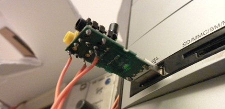
[Scott] bought a cheap USB sound card dongle on eBay (although a built-in sound card will do) and wired up the tip and ring of the plug to the microcontroller. The data is sent from the microcontroller a lot like Morse code – a short gap between pulses is a zero, a long gap is a one. This is parsed by a Python script using PyAudio. Synchronization, timing, and calibration is automatic because of a 10-bit ‘packet header’ explained in this video.

Continue reading “Sound Card Microcontroller/PC Communication” →