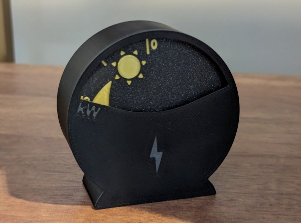
[Jens] wanted a subscriber counter for his YouTube channel. He could have gone with a simple OLED, LCD, or LED display, but he wanted something more tactile and interesting. So he built a mechanical 7-segment display instead!
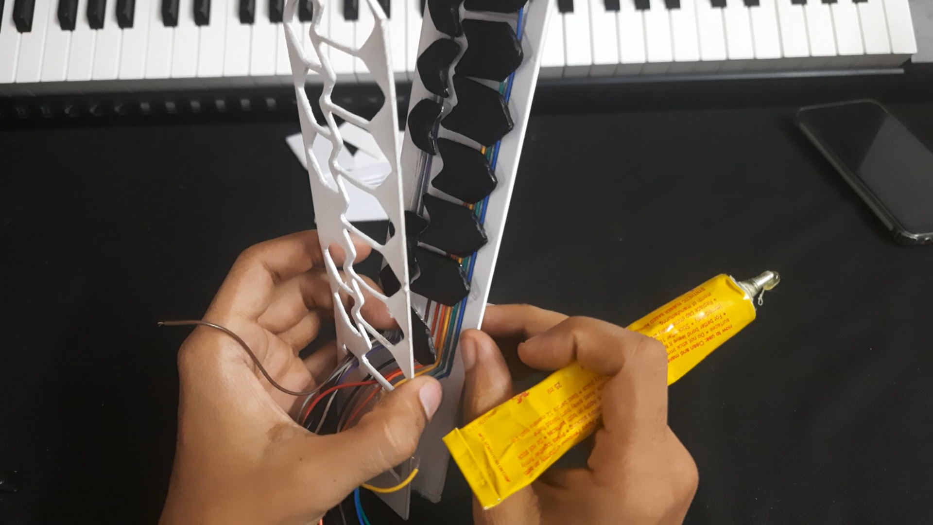
Currently, [Jens]’s channel is in the four-digit subscriber range, so he planned to build a four-digit display. He started by searching for existing projects in this space, and came across the designs of [shiura] on Thingiverse. [shiura] had a 3D printed cam-driven 7-segment digit that runs on a single servo motor. Once armed with four of the digits, he hooked them up to a Pi Pico W to drive them all with four servo outputs. The Pico W is responsible for querying the channel subscriber count online, and updating the display in turn.
It’s a neat build, and [Jens] learned some things along the way—like how Super Lube seemed to ruin filament for him. Ultimately, the build came good, and it looks great. We’ve seen some other mechanical 7-segment builds before, too!


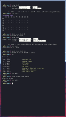 BreadboardOS is built on top of FreeRTOS. It’s aim is to enable quick prototyping with the Pi Pico. Don’t confuse operating system with a graphical environment — BreadboardOS is command-line based. You’d typically interface with it via a serial terminal emulator, but joy of joys, it does support color!