For those new to fields like robotics or aerospace, it can seem at first glance that a problem like moving a robot arm or flying an RC airplane might be simple problems to solve. It turns out, however, that control of systems like these can get complicated quickly; so much so that these types of problems have spawned their own dedicated branch of engineering. As controls engineers delve into this field, one of their initial encounters with a control system is often with the PID controller, and this open source project delivers two of these general-purpose controllers in one box.
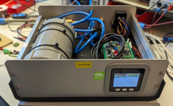
The dual-channel PID controller was originally meant as a humidity and temperature controller and was based on existing software for an ATmega328. But after years of tinkering, adding new features, and moving the controller to an ESP32 platform, [knifter] has essentially a brand new piece of software for this controller. Configuring the controller itself is done before the software is compiled, and it includes a GUI since one of the design goals of the project was ease-of-use. He’s used it to control humidity, temperature and CO2 levels in his own work at the University of Amsterdam, but imagines that it could see further use outside of his use cases in things like reflow ovens which need simple on/off control or for motors which can be controlled through an H-bridge.
The PID controller itself seems fairly robust, and includes a number of features that seasoned controls engineers would look for in their PID controllers. There are additionally some other open-source PID controllers to take a look at like this one built for an Arduino, and if you’re still looking for interesting use cases for these types of controllers one of our favorites is this PID controller built into a charcoal grill.