As portable as keyboards have gotten, you still need some place to put the thing — some kind of bag for travel, and a flat surface for using it. Well, it doesn’t get much more portable than a hat keyboard, now does it?
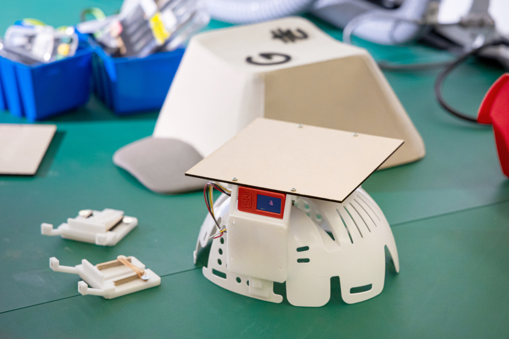 Every October 1st, Google Japan likes to celebrate the 101-key keyboard by building something revolutionary off the top of their heads. (10/1… 101… get it?) This year was no exception — they created the GCAPS, a ballcap-like device with a single switch inside.
In order to use it, you spin the hat left and right until the desired character is reached, and the rotation is detected by a gyroscope. Then you press down on the top of the hat to send the key codes via Bluetooth.
Under the hood, the hat uses an M5Stick C Plus and, to our dismay, a micro switch that wasn’t even made by Cherry. Oh well — we landed on the clicky side, so that’s great in our book. Surprisingly, there exists a skull cap/hat skeleton thing on which to build a platform for pressing down on the switch. Just like the teaboard and the long boi keyboards, this thing is completely open source.
Since it types in Japanese, there’s no word on whether it types in all caps, though we like to think that it would given the object it represents. Be sure to check out the product reveal video after the break.
Continue reading “Hats Off To Another Weird Keyboard From Google Japan”