When we announced the Hackaday Prize with its Best Product category, [PK] polled his wife and co-workers about the idea of making a desktop monitor using 6″ 800×600 ePaper, which he has since built and calls the PaperBack. One such requirement for a monitor is to be able to connect to it using one of the usual desktop methods: VGA, DVI or HDMI. Given his previous experience making his own VGA card for the 2015 prize, he went with that. HDMI is in the works.
But it ended up being more than a desktop monitor. He first made a power and breakout board that a VGA input board would eventually connect to. To test it, he included a socket for plugging in an ESP32. With only one bodge he had the Hackaday logo displayed on the ePaper. He also now had the option of using it as a wireless internet connected display.
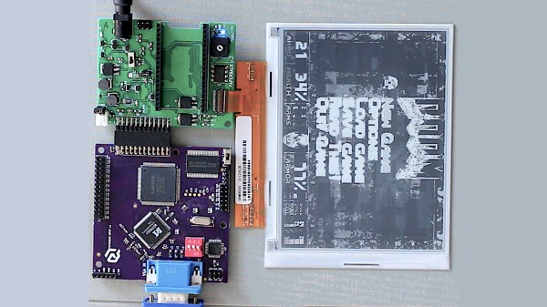
Moving on to VGA support, [PK] made a VGA input board using the MST9883 chip, which does the A/D conversion of the VGA RGB graphics signal and also recovers a pixel sampling clock from the HSYNC. His new VGA ePaper monitor has to identify itself to the VGA source, telling it dimensions, resolution and so on. This is called the EDID and was handled by the addition of an Atmel ATmega328 to the board. To finish it off, an LCMXO1200C FPGA does the high-speed conversions with the help of a 4 MBit SRAM framebuffer.
His very first test involved simply displaying the Hackaday logo using the ESP32, but now with the VGA input board he has it displaying Doom. Since it’s using ePaper it has only a 1-second refresh rate but it’s hard to come up with a more awesome way to proved that it works. He can also unplug it at any time and walk away with the latest screenshot intact. See it for yourself in the video below.
Continue reading “Hackaday Prize Entry: PaperBack Desktop EPaper Monitor”