Back in the early days of the home computer revolution, data was commonly saved on tape. Even better, those tapes would make an almighty racket if you played them on a stereo, because the data was stored in an audio format. The Simple Universal Modem from [Anders Nielsen] is built to work in a similar way, turning data into audio and vice versa.
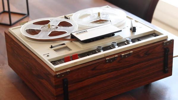
The project consists of a circuit for modulating data into audio, and demodulating audio back into data. It’s “universal” because [Anders] has designed it to be as format-agnostic as possible. It doesn’t matter whether you want to store data on a digital voice recorder, a cassette deck, or an old reel-to-reel. This build should work fairly well on all of them!
On the modulation side of things, it’s designed to be as analog-friendly as possible. Rather than just spitting out rough square waves, it modulates them into nice smooth sine waves with fewer harmonics. On the demodulation side, it’s got an LM393 comparator which can read data on tape and spit out a clean square wave for easy decoding by digital circuitry.
If you find yourself trying to recover old data off tapes, or writing to them for a retrocomputing project, this build might be just what you need. [Anders] even goes as far as demonstrating its use with an old reel-to-reel deck in a helpful YouTube video.
There really were some weird ways of storing data way back when. Just ask IBM. Video after the break.
Continue reading “Simple Universal Modem Helps Save And Load Data From Tape”