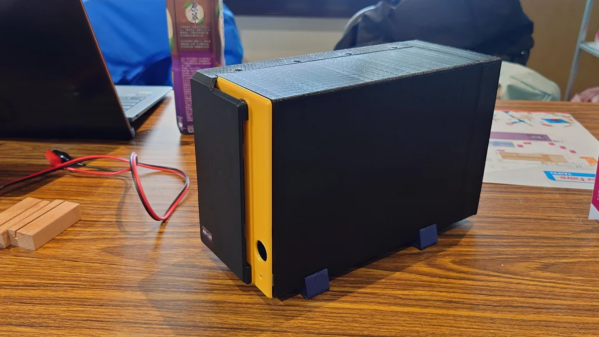
Building your own network attached storage (NAS) for personal use isn’t all that difficult. A single board computer, a hard disk and a power supply in an enclosure is all the hardware you need. Then, choose from one of several open source NAS software solutions and you’re up and running. [tobychui] decided to notch things up by designing a NAS that really looks like a NAS. It’s tailored to his specific requirements and looks like a professional product to boot. The design features dual 3.5 inch HDD bays, a small footprint, is low cost, compatible with a variety of single board computers, and can handle high data transfer speeds by using RAM and SD card for buffering.
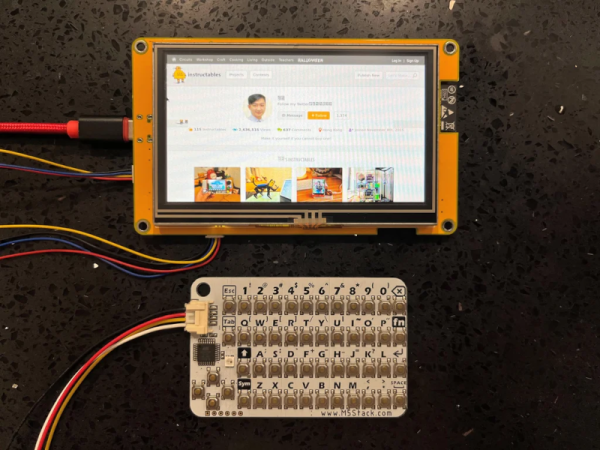
Not only has he done a great job with the hardware design, but he’s also developed a companion software for the NAS. “ArozOS” is a web desktop operating system that provides full-fledged desktop experience within a browser. ArozOS has a great user interface and features a lot of networking, file, disk management and security functions. He has also developed a launcher application to enable over-the-air (OTA) software updates.
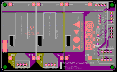 Assembling the device will need some planning and preparation, even though most of the hardware is off the shelf. You will need a SATA to USB 2.0 adapter, a SBC (Orange Pi Zero, Raspberry Pi 4, Orange Pi Zero 2, etc) , three buck converters — one each to provide 12 V to the two hard disks and a third to provide 5 V to the SBC. You’ll also need a 12 V / 6 A or 24 V / 3 A external power brick, or a USB-C 65 W GaN charger with a triggering module to set the desired voltage and current.
There is also one custom power distribution board which is essentially a carrier board to mount the buck converters and connectors for power and USB data. For the 3D prints, [tobychui] recommends printing at the highest resolution for a nice finish.
The off the shelf SATA to USB adapter will need to be taken apart before it can be fixed to the 3D printed SATA adapter plate and might pose the most challenge during construction, but the rest of the assembly is fairly straightforward. Once assembly is complete, [tobychui] walks you through installation of the ArozOZ software, mounting the drives and making them accessible over the network.
Have you got your data backup act in order ? If not, it’s still not too late to make it a new Year’s resolution. And if you need help figuring things out, check out New Year Habits – What Do You Do For Data Storage?
Continue reading “Building A NAS That Really Looks Like A NAS”