Remove Security Issues From Untrusted USB Connections

USB has become pretty “universal” nowadays, handling everything from high-speed data transfer to charging phones. There are even USB-powered lava lamps. This ubiquity doesn’t come without some costs, though. There have been many attacks on smartphones and computers which exploit the fact that USB is found pretty much everywhere, and if you want to avoid these attacks you can either give up using USB or do what [Jason] did and block the data lines on the USB port.

USB typically uses four wires: two for power and two for data. If you simply disconnect the data lines, though, the peripheral can’t negotiate with the host for more power and will limp along at 0.5 watts. However, [Jason] discovered that this negotiation takes place at a much lower data rate than normal data transfer, and was able to put a type of filter in between the host and the peripheral. The filter allows the low-frequency data transfer pass through but when a high-frequency data transfer occurs the filter blocks the communication.

[Jason] now has a device that can allow his peripherals to charge at the increased rate without having to worry about untrusted USB ports (at an airport or coffee shop, for example). This simple device could stop things like BadUSB from doing their dirty work, although whether or not it could stop something this nasty is still up in the air.

USB Switch

Reverse Engineering How A USB Switch Switches

[Daniel] found himself with a need to connect a single USB device to two Linux servers. After searching around, he managed to find an inexpensive USB switch designed to do just that. He noticed that the product description mentioned nothing about Linux support, but he figured it couldn’t be that hard to make it work.

[Daniel] started by plugging the device into a Windows PC for testing. Windows detected the device and installed an HID driver automatically.  The next step was to install the control software on the Windows system. This provided [Daniel] with a tray icon and a “switch” function. Clicking this button disconnected the HID device from the Windows PC and connected the actual USB device on the other side of the USB switch. The second computer would now have access to the HID device instead.

[Daniel] fired up a program called SnoopyPro. This software is used to inspect USB traffic. [Daniel] noticed that a single message repeated itself until he pressed the “switch” button. At that time, a final message was sent and the HID device disconnected.

Now it was time to get cracking on Linux. [Daniel] hooked up the switch to a Linux system and configured a udev rule to ensure that it always showed up as /dev/usbswitch. He then wrote a python script to write the captured data to the usbswitch device. It was that simple. The device switched over as expected. So much for having no Linux support!

Teensy Adds S/PDIF To Library

With Arduino library support on an ARM Cortex M4 processor, it’s no surprise that we’re fans of the Teensy 3.1. And lately, [Paul Stoffregen] has been building out the Audio Library for this platform, making it even more appealing to the synth / audio geeks among us. And now, with just the addition of a highfalutin LED and some software, the Teensy can output digital audio over optical fiber.

S/PDIF, and more specifically optical TOSLINK, uses LED light sent down an optical fiber to encode audio data. The advantage of this over any voltage-level signals (like with regular wires) is that the source and destination devices aren’t electrically connected at all, which gets rid of the dreaded ground loop hum and any RF interference.

An S/PDIF audio data stream is a bit complex, but if you’re interested [Micah Scott] has a fantastic dissection of it up on her blog. Of course, you don’t have to know anything about any of that to simply use S/PDIF with the Teensy Audio Library.

We love open source hardware and software because of the collaborations that make ultra-rapid development of niche stuff like this possible. You can follow along with the development of the Teensy’s S/PDIF capabilities on the PJRC forum. Contributor [Frank B] modestly claims that “everything was already on the internet”, but that doesn’t make it any less cool that they got from zero to working library in a few weeks. (And note the clever use of a precomputed lookup table for speed.)

LED_TOSLINK2On the hardware side, [Paul] has posted up his adapter board for a cheap, but very professional looking, optical TOSLINK sender. But if you’re feeling ghetto, you can simply use a red LED pointed just right into the optical cable.

The end result? Lossless transmission of CD-quality audio from an Arduino-esque microcontroller, sent on a beam of light, for less than the cost of a latté.

Excruciating Quest Turns Chromebook Pixel IPS Into Exquisite Extra Monitor

[Shen] wanted an extra monitor at his desk, but not just any monitor. He wanted something particularly special and unquestionably refined. Like any super-power-possessing engineer he set out to scratch his hacking itch and was sucked into a multi-year extravaganza. For the love of everything hardware we’re glad this one came in on the weekend. If we had spent all that time drooling during a weekday we’d be so far behind.

The final product is a desktop monitor on an articulated arm. It features a Chromebook Pixel’s IPS display in a custom-crafted case everything. The journey started out with two different LCD units, the first from a Dell L502x replacement display using a generic LVDS board. The results were meh; washed out colors and obvious pixellation, with display adjustments that left [Shen] with a grimace on his mug. Installment two was an iPad Retina display. This iteration required spinning his own boards (resulting in [Shen’s] discovery of OSH Park). Alas, 9.7″ was too small coupled with short-cable-requirements making this version a no-go.

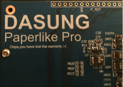
chromebook-pixel-ips-driver-boardAnd so we arrive at the meat and potatoes of this one. [Shen] identified the IPS LCD display on Google’s first Chromebook Pixel laptop as the object of his desire. The hack takes him through sourcing custom display cables, spinning rev after rev of his own board, and following Alice down the rabbit hole of mechanical design. Nothing marginal is good enough for [Shen], we discovered this with his project to get real audio out of a computer. He grinds away at the driver board, the case design, the control presentation, and everything else in the project until perfection was reached. This work of art will stand the test of time as a life fixture and not just an unappreciated workhorse.

This one is not to me missed. Head over to [Shen’s] project entry on Hackaday.io (don’t forget to give him a skull for this) and his blog linked at the top. We need to celebrate not only the people who can pull off such amazing work. But also the ones who do such a great job of sharing the story both for our enjoyment, and to inspire us.

Wireless Trackpad Looks Like Fingernail Polish

All hands are on deck over at MIT where a very handy new trackpad has been created that will be able to give users a free hand to do other tasks. The device is called the NailO and attaches to one’s thumbnail, which allows the user an easy and reportedly natural way to use a trackpad while your hands are full, dirty, or otherwise occupied.

The device reportedly works like any normal trackpad, but is about the size of a quarter and attaches to the thumbnail in such a way that it takes advantage of the natural motion of running an index finger over the thumbnail. It communicates via Bluetooth radio, and has four layers which all go hand-in-hand: an artistic covering (to replicate the look of a painted fingernail), the sensors, the circuitry, the battery, and presumably an adhesive of some sort.

Details are quite sparse, but the device is scheduled to make its debut at the Computer Human Interaction conference in Seoul, South Korea very soon. If it can be made less bulky (although it’s somewhat uncomfortable to call something smaller than a quarter “bulky”) this might be, hands down, the next greatest evolution in mouse technology since multi-touch. We have to hand it to MIT for coming up with such a unique wearable!

1337-sp34k Keyboard

What started off as a quick prank-hack to re-map a colleague’s keyboard turned into a deep dive in understanding how keyboards work. [ch00f] and his other work place colleagues are in a habit of pulling pranks on each other. When [ch00f]’s buddy, who is an avid gamer and montage parody 1337-sp34k (leet speak) fan, went off on a holiday, [ch00f] set about re-mapping his friend’s keyboard to make it spit out words his friend uses a lot – “SWAG” “YOLO” and “420”. But remapping in software is too simple, his hack is a hardware remapping!

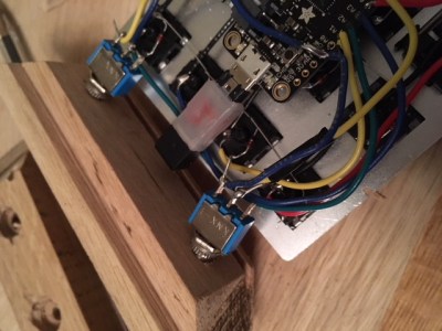
The keyboard in question used mechanical keys mounted on a keyboard sized PCB. Further, it was single sided, with jumper links used in place of front side tracks. This made hacking easier. The plan was to use keys not commonly used – Scroll Lock, Print Screen, and Pause/Break – and get them to print out the words instead. The signal tracks from these three keys were cut away and replaced with outputs from a microcontroller. The original connections were also routed to the microcontroller, and a toggle switch used to select between the remapped and original versions. This was eventually not implemented due to a lack of space to install the toggle switch. [ch00f] decided to just replace the keyboard if his friend complained about the hack. A bit of work on the ATMega PCB and firmware, and he was able to get the selected keys to type out SWAG, YOLO and 420.

And this is where a whole can of worms opened up. [ch00f] delves in to an explanation on the various issues at hand – keyboard scanning/multiplexing, how body-diodes in switching FET’s affected the scanning, ghosting and the use of blocking diodes. Towards the end, he just had the word SWAG activated by pressing the Pause/Break key. But he does get to the bottom of why the keyboard was behaving odd after he had wired in his hack, which makes for some interesting reading. Don’t miss the video of the hack in action after the break.

Continue reading “1337-sp34k Keyboard”

Using I2C Addresses As Chip Selects

I2C has a seven-bit address space, and you’re thinking “when do I ever need more than 127 devices on a pair of wires?” So you order up some parts only to find that they have one, two, or three user-configurable address pins for any given device type. And you need a bunch more than four or eight capacitive sensor buttons on your project. What do you do?

If you’re reader [Marv G], you think outside the box and realize that you can change the addresses on the fly by toggling address pins high and low with your microcontroller. That is, you can use a single I2C address pin for each device as a chip select signal just like you would have with SPI.

That’s it, really. [Marv G] goes through all of the other possible options in his writeup, and they’re all unsavory: multiple I2C busses, a multiplexer, buying different sensors, or changing micros. None of these are as straightforward as just running some more wires and toggling these with your micro.

We’d even go so far as to suggest that you could fan these chip select lines out with a shift register or one of those 1-of-N decoder chips, depending on how many I2C devices you need to chip-selectify. (We’re thinking 74HC595 or 74HC154.)

Along the way, we found this nice list of the number of address pins for a bunch of common peripherals provided by [LadyAda], in case you don’t believe us about how ubiquitous this problem is. How many devices on that list have one (1!!) address pin?

At the end of his post, [Marv G] asks if anyone else has thought of this chip select trick before. We hadn’t. Here’s your chance to play the smart-ass in the comments.