An Unconference Badge That’s Never Gonna Give You Up

When your publication is about to hold a major event on your side of the world, and there will be a bring-a-hack, you abruptly realise that you have to do just that. Bring a hack. With the Hackaday London Unconference in the works this was the problem I faced, and I’d run out of time to put together an amazing PCB with beautiful artwork and software-driven functionality to amuse and delight other attendees. It was time to come up with something that would gain me a few Brownie points while remaining within the time I had at my disposal alongside my Hackaday work.

Since I am a radio enthusiast at heart, I came up with the idea of a badge that the curious would identify as an FM transmitter before tuning a portable radio to the frequency on its display and listening to what it was sending. The joke would be of course that they would end up listening to a chiptune version of [Rick Astley]’s “Never gonna give you up”, so yes, it was going to be a radio Rickroll.

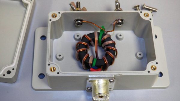
The badge internals.

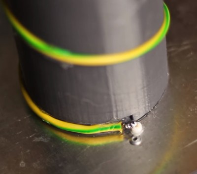
I evaluated a few options, and ended up with a Raspberry Pi Zero as an MP3 player through its PWM lines, feeding through a simple RC low-pass filter into a commercial super-low-power FM transmitter module of the type you can legally use with an iPod or similar to listen on a car radio. To give it a little bit of individuality I gave the module an antenna, a fractal design made from a quarter wavelength of galvanised fence wire with a cut-off pin from a broken British mains plug as a terminal. The whole I enclosed in a surplus 8mm video cassette case with holes Dremmeled for cables, with the FM module using its own little cell and the Pi powered from a mobile phone booster battery clipped to its back. This probably gave me a transmitted field strength above what it should have been, but the power of those modules is so low that I am guessing the sin against the radio spectrum must have been minor.

At the event, a lot of people were intrigued by the badge, and a few of them were even Rickrolled by it. But for me the most interesting aspect lay not in the badge itself but in its components. First I looked at making a PCB with MP3 and radio chips, but decided against it when the budget edged towards £20 ($27). Then I looked at a Raspberry Pi running PiFM as an all-in-one solution with a little display HAT, but yet again ran out of budget. An MP3 module, Arduino clone, and display similarly became too expensive. Displays, surprisingly, are dear. So my cheapest option became a consumer FM module at £2.50 ($3.37) which already had an LCD display, and a little £5 ($6.74) computer running Linux that was far more powerful than the job in hand demanded. These economics would have been markedly different had I been manufacturing a million badges, but made a mockery of the notion that the simplest MCU and MP3 module would also be the cheapest.

Rickrolling never gets old, it seems, but evidently it has. Its heyday in Hackaday projects like this prank IR repeater seems to have been in 2012.

Hybrid Technique Breaks Backscatter Distance Barrier

Low cost, long range, or low power — when it comes to wireless connectivity, historically you’ve only been able to pick two. But a group at the University of Washington appears to have made a breakthrough in backscatter communications that allows reliable data transfer over 2.8 kilometers using only microwatts, and for pennies apiece.

For those unfamiliar with backscatter, it’s a very cool technology that modulates data onto RF energy incident from some local source, like an FM broadcast station or nearby WiFi router. Since the backscatter device doesn’t need to power local oscillators or other hungry components, it has negligible power requirements. Traditionally, though, that has given backscatter devices a range of a few hundred meters at most. The UW team, led by [Shyamnath Gollokota], describe a new backscatter technique (PDF link) that blows away previous records. By combining the spread-spectrum modulation of LoRa with the switched attenuation of incident RF energy that forms the basis for backscatter, the UW team was able to cover 2800 meters for under 10 microwatts. What’s more, with printable batteries or cheap button cells, the backscatter tags can be made for as little as 10 cents a piece. The possibilities for cheap agricultural sensors, ultracompact and low power wearable sensors, or even just deploy-and-forget IoT devices are endless.

We’ve covered backscatter before, both for agricultural uses and for pirate broadcasting stations. Backscatter also has also seen more cloak and dagger duty.

Continue reading “Hybrid Technique Breaks Backscatter Distance Barrier”

A Fully Featured, Fifty Dollar QRP Radio

QRP radio operators try to get maximum range out of minimal power. This term comes from the QRP Q-code, which means “reduce power.” For years, people have built some very low-cost radios for this purpose. Perhaps the best known QRP kit is the Pixie, which can be found for less than $3 on eBay.

The QCX is a new DIY QRP radio kit from QRP Labs. Unlike the Pixie, it has a long list of features. The QCX operates on the 80, 60, 40, 30, 20, or 17 meter bands at up to 5W output power. The display provides tuning information, an S-meter, and a CW decoder. An on-board microswitch functions as a basic Morse key, and external Iambic or straight keys are also supported. An optional GPS can be used as a frequency reference.

The radio is based around the Silicon Labs Si5351A Clock Generator, a PLL chip with three clock outputs ranging from 2.5 kHz to 200 MHz. The system is controlled by an Atmel ATmega328P.

Demand for the kit has been quite high, and unfortunately you’ll have to wait for one. However, you can put down your $49 and learn Morse code while waiting for it to ship. While the project does not appear to be open source, the assembly instructions [PDF warning] provide a full schematic.

Antenna Basics By Whiteboard

Like a lot of people, [Bruce] likes radio controlled (RC) vehicles. In fact, many people get started in electronics motivated by their interest in RC. Maybe that’s why [Bruce] did a video about antenna basics where he spends a little more than a half hour discussing antennas. You can see the video below.

[Bruce] avoids any complex math and focuses more on intuition about antennas, which we like. Why does it matter that antennas are cut to a certain length? [Bruce] explains it using a swing and a grandfather clock as an analogy. Why do some antennas have gain? Why is polarization important? [Bruce] covers all of this and more. There’s even a simple experiment you can do with a meter and a magnet that he demonstrates.

Continue reading “Antenna Basics By Whiteboard”

The Things Network Sets 702 Km Distance Record For LoRaWAN

Many of us will have at some time over the last couple of years bought a LoRaWAN module or two to evaluate the low power freely accessible wireless networking technology. Some have produced exciting and innovative projects using them while maybe the rest of us still have them on our benches as reminders of projects half-completed.

If your LoRaWAN deployment made it on-air, you’ll be familiar with the range that can be expected. A mile or two with little omnidirectional antennas if you are lucky. A few more miles if you reach for something with a bit of directionality. Add some elevation, and range increases.

A couple of weeks ago at an alternative society festival in the Netherlands, a balloon was launched with a LoRaWAN payload on board that was later found to have made what is believed to be a new distance record for successful reception of a LoRaWAN packet. While the balloon was at an altitude of 38.772 km (about 127204.7 feet) somewhere close to the border between Germany and the Netherlands, it was spotted by a The Things Network node in Wroclaw, Poland, at a distance of 702.676km, or about 436 miles. The Things Network is an open source, community driven effort that has built a worldwide LoRaWAN network.

Of course, a free-space distance record for a balloon near the edge of space might sound very cool and all that, but it’s not going to be of much relevance when you are wrestling with the challenge of getting sensor data through suburbia. But it does provide an interesting demonstration of the capabilities of LoRaWAN over some other similar technologies, if a 25mW (14dBm) transmitter can successfully send a packet over that distance then perhaps it might be your best choice in the urban jungle.

If you’re curious about LoRaWAN, you might want to start closer to home and sniff for local activity.

Doppler Module Teardown Reveals The Weird World Of Microwave Electronics

Oscillators with components that aren’t electrically connected to anything? PCB traces that function as passive components based solely on their shape? Slots and holes in the board with specific functions? Welcome to the weird and wonderful world of microwave electronics, brought to you through this teardown and analysis of a Doppler microwave transceiver module.

We’ve always been fascinated by the way conventional electronic rules break down as frequency increases. The Doppler module that [Kerry Wong] chose to pop open, a Microsemi X-band transceiver that goes for about $10 on eBay right now, has vanishingly few components inside. One transistor for the local oscillator, one for the mixer, and about three other passives are the whole BOM. That the LO is tuned by a barium titanate slug that acts as a dielectric resonator is just fascinating, as is the fact that PB traces can form a complete filter network just by virtue of their size and shape. Antennas that are coupled to the transceiver through an air gap via slots in the board are a neat trick too.

[Kerry] analyzes all this in the video below and shows how the module can be used as a sensor. If you need a little more detail on putting these modules to work, we’ve got some basic circuits you can check out.

Continue reading “Doppler Module Teardown Reveals The Weird World Of Microwave Electronics”

Scribble Your Way To Quick Printed Circuit Boards

There are a variety of techniques employed by electronic constructors seeking the convenience of a printed circuit board without the inconvenience of making a printed circuit board. Dead bug style construction in which the components float on a spiders-web of soldered leads above a ground plane is one, Manhattan style construction in which pads made from small cut squares of bare copper-clad PCB are glued on top of a groundplane is another.

[Freestate QRP] has another take on this type of electronics, with what he calls “Scribble style” construction. He cuts away copper from bare board to create pads and rudimentary tracks, and for him the magic ingredient comes from his choice of an engineer’s scribe to do the job. This is where the “scribble” comes from, creating a pad is as simple as drawing it with the scribe.

Of course, this technique is not entirely new, constructors have been doing this type of work for years with Dremel tools, hand engraving tools, and similar. If you’ve ever tried to do it with a knife or scalpel you will know that it’s hardly an easy task with those hand tools so the prospect of another one doing a better job is rather interesting. He’s ready and able to demonstrate it in action, showing us a couple of RF circuits using the technique.

Have you tried this technique, or one like it? How did you get on, tell us in the comments. Meanwhile, you might like to read our own [Dan Maloney]’s look at dead bug and Manhattan construction.