
One thing has stayed with the James Bond movie franchise through the decades: Mr. Bond always has the most wonderful of gadgets. Be it handheld, car-based, or otherwise, there’s always something to thrill that is mostly believable.
The biggest problem with all of those gadgets is that they mark Commander Bond as an obvious spy. “So Mr. Bond, I see you have a book with many random five character groups. Nothing suspicious about that at all!” And we all know that import/export specialists often carry exploding cufflinks or briefcases full of unknown electronics in hidden compartments.
Just as steganography hides data in plain sight, the best spy gadgets are the ones that don’t seem to be a spy gadget. It is no wonder some old weapons are little more than sticks or farm implements. You can tell a peasant he can’t have a sword, but it is hard to ban sticks.
Imagine you were a cold war era spy living in a hostile country with a cover job with Universal Exports. Would you rather get caught with a sophisticated encryption machine or an ordinary consumer radio? I’m guessing you went with the radio. You aren’t the only one. That was one of the presumed purposes to the mysterious shortwave broadcasts known as number stations. These were very common during the cold war, but there are still a few of them operating.
Continue reading “Secret Radio Stations By The Numbers”

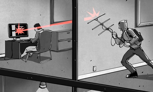
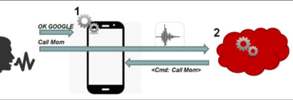
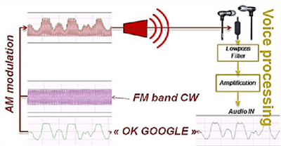 The ubiquitous Apple earbuds have a single wire for a microphone input, and this is the attack vector used by the researchers. With a 50 Watt VHF power amplifier (available for under $100, if you know where to look), a software defined radio with Tx capability ($300), and a highly directional antenna (free clothes hangers with your dry cleaning), a specially crafted radio message can be transmitted to the headphone wire, picked up through the audio in of the phone, and understood by Siri, Cortana, or Google Now.


