CATS is a new communication and telemetry standard intended to surpass the current Automatic Packet Reporting System (APRS) standard by leveraging modern, super-cheap Frequency Shift Keying (FSK) transceivers rather than standard FM units. The project is in the early stages, but as of this writing, there is a full open source software stack and reference hardware for both Raspberry Pi-based gateway devices and an STM32-based mobile device.
From a radio perspective, CATS uses raw FSK rather than the inefficient AFSK used by APRS. A real killer for channel utilization is the PTT time; this is the dead time around a packet APRS requires for ‘keying up’ and ‘keying down.’ The CATS standard is aggressive with PTT timing, enabling the channel to get going on sending the data sooner.
Additionally, compared to APRS, the packet baud rate increases from 1200 baud to 9600 baud. Other key points are using LDPC encoding for forward error correction and data whitening (a useful PDF guide from Ti) to smooth over any burst errors.
One of the neat concepts of APRS is the APRS-IS (APRS Internet service). This enables amateur radio services to be connected over the Internet, vastly improving range. The CATS equivalent is called FELINET (if you’re not spotting all the ‘cat’ references by now, go and get another coffee). Together with the I-gate hardware, FELINET bridges the CATS radio side with the current APRS network. As FELINET expands to more than the current few dozen nodes, APRS services will no longer be required, and FELINET may well replace it. Interestingly, all software for FELINET, the APRS relay, and the I-Gate firmware are written in Rust. We told you learning Rust was going to be worth the effort!
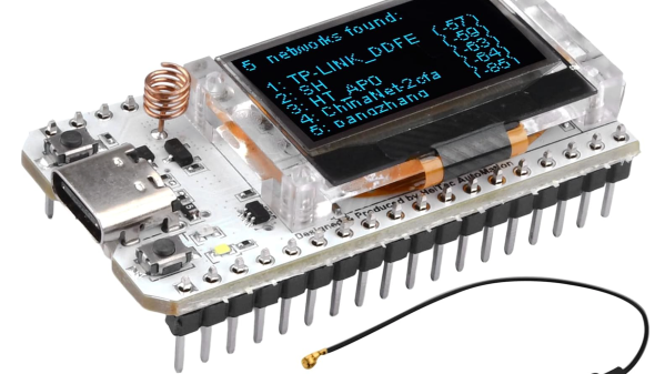
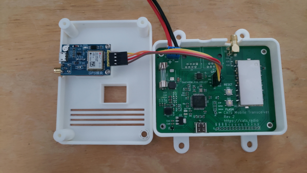
On the reference hardware side of things, the CATS project has delivered a Raspberry Pi hat, which uses a 1 watt RF4463 transceiver and supporting passives. The design is about as simple as it can be. A mobile transceiver version uses an STM32 micro to drive the same RF4463 but with supporting power supplies intended to run from a typical automotive outlet. Both designs are complete KiCAD projects. Finally, once you’ve got some hardware in place and the software installed, you will want to be able to debug it. CATS has you covered with an RTL-SDR I-Gate module, giving you an independent packet log.
APRS is quite mature, and we’ve seen many hacks on these pages. Here’s an earlier APRS IGate build using a Raspberry Pi. Need to hook up your PC to a cheap Chinese transceiver? You need the all-in-one cable. As with many things amateur-radio-oriented, you can get playing cheaply.