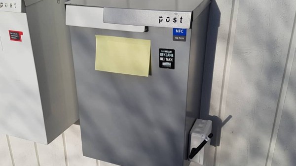
As more of the world’s communication moves into the electronic realm, a casualty has come in the physical mail. Where once each new day might have brought with it a bulging mailbox, today it’s not uncommon for days to pass with not even so much as a bill or a coupon book. For [Eivholt] this presents a problem: he doesn’t want to miss a parcel but most visits to the mailbox are futile. His solution is a LoRa-connected mailbox monitor that sips power from a pair of AAA batteries to the extent that so far it’s run for over two years on a single set.
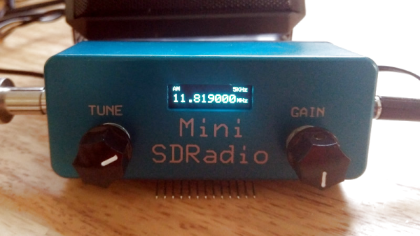
At its heart is a single board, a Talk2 Whisper Node. This packs a low-power version of the ATmega328 microcontroller alongside a LoRa radio and an efficient power regulator allowing it to draw only 8.70 uA in standby mode, waking up only for extremely short periods to check for mail and report via LoRa to The Things Network. The sensor is simply a microswitch, selected after finding a reed switch problematic to install. Finally an SDR was used to debug the operation of the radio.
The write-up also provides an introduction to extreme low power projects, including some tips on measuring such tiny currents. Even if you have no interest in a mailbox, any tricks that can help maximize power efficiency are always worth taking a look at. Check out the video after the break to see this radio-equipped mailbox in action.
Continue reading “AAA Powered LoRa Mailbox Sensor Goes The Distance”