Next time you get a new device and excitedly unwrap its little poly-wrapped power supply, remember this: for every switch-mode power supply you plug in, an amateur radio operator sheds a tear. A noisy, broadband, harmonic-laden tear.
The degree to which this fact disturbs you very much depends upon which side of the mic you’re on, but radio-frequency interference, or RFI, is something we should all at least be aware of. [Josh (KI6NAZ)] is keenly aware of RFI in his ham shack, but rather than curse the ever-rising noise floor he’s come up with some helpful tips for hunting down and eliminating it – or at least reducing its impact.
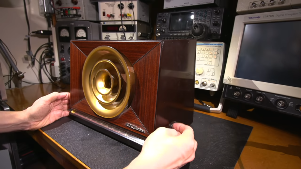
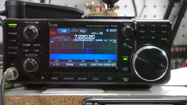
Attacking the problem begins with locating the sources of RFI, for which [Josh] used the classic “one-circuit-at-a-time” approach – kill every breaker in the panel and monitor the noise floor while flipping each breaker back on. This should at least give you a rough idea of where the offending devices are in your house. From there, [Josh] used a small shortwave receiver to locate problem areas, like the refrigerator, the clothes dryer, and his shack PC. The family flat-screen TV proved to be quite noisy too. Remediation techniques include wrapping every power cord and cable around toroids or clamping ferrite cores around them, both on the offending devices and in the shack. He even went so far as to add a line filter to the dryer to clamp down on its unwanted interference.
Judging by his waterfall displays, [Josh]’s efforts paid off, bringing his noise floor down from S5 to S1 or so. It’s too bad he had to take matters into his own hands – it’s not like the FCC and other spectrum watchdogs don’t know there’s a problem, after all.
Continue reading “The RFI Hunter: Looking For Noise In All The Wrong Places”