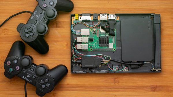
[Jeff Geerling] has been following the various open source time projects for some time now, and is finally able to demonstrate a working and affordable solution for nanoseconds-accurate timekeeping in your local lab. The possibility of a low-cost time server came about with the introduction of the Raspberry Pi CM4 compute module back in Oct 2020, whose Broadcom network chip (BCM54210PE) supports PTP (Precision Time Protocol, IEEE-1588) 1PPS output and hardware-based time stamping. Despite the CM4 data sheet specifying PTP support, it wasn’t available in the kernel. An issue was raised in Feb last year, and Raspberry Pi kernel support was finally released this month.
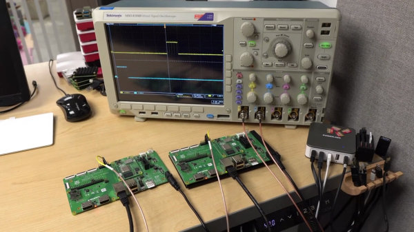
[Jeff] demonstrates how easy it is to get two CM4 modules to synchronize to within a few tens of nanoseconds in the video below the break. That alone can be very useful on many projects. But if you want really stable and absolute time, you need a stratum 1 external source. These time servers, called grandmasters in PTP nomenclature, have traditionally been specialized pieces of kit costing tens of thousands of dollars, using precision oscillators for stability and RF signals from stratum 0 devices like navigation satellites or terrestrial broadcast stations to get absolute time. But as Lasse Johnsen, who worked on the kernel updates remarks in the video:
In 2022 these purpose-built grandmaster clocks from the traditional vendors are about as relevant as the appliance web servers like the Raq and Qube were back in 1998.
It is now possible to build your own low-cost stratum 1 time server in your lab from open source projects. Two examples shown in the video. The Open Time Server project’s Timecard uses a GNSS satellite receiver and a Microchip MAC-SA5X Rubidium oscillator. If that’s overkill for your projects or budget, the Time4Pi CM4 hat is about to be release for under $200. If accurate time keeping is your thing, the technology is now within reach of the average home lab. You can also add PTP to a non-CM4 Raspberry Pi — check out the Real-Time HAT that we covered last year.
Continue reading “Stratum 1 Grandmaster Time Server On A Budget”

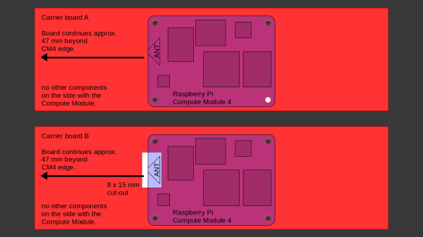
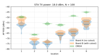 After setting up some test locations and writing a few scripts for ease of testing, [Avian] recorded the experiment data. Having that data plotted, it would seem that, while presence of an under-antenna cutout helps, it doesn’t affect RSSI as much as the module placement does. Of course, there’s way more variables that could affect RSSI results for your own designs – thankfully, the scripts used for logging are available, so you can test your own setups if need be.


