We all know the Hollywood trope of picking a lock with a paperclip, and while it certainly is doable, most reputable locks require slightly more sophisticated tools to pick effectively. That’s not to say that wire is off the table for locksports, though, as this cool lock-picking robot demonstrates.
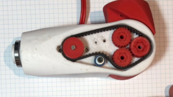
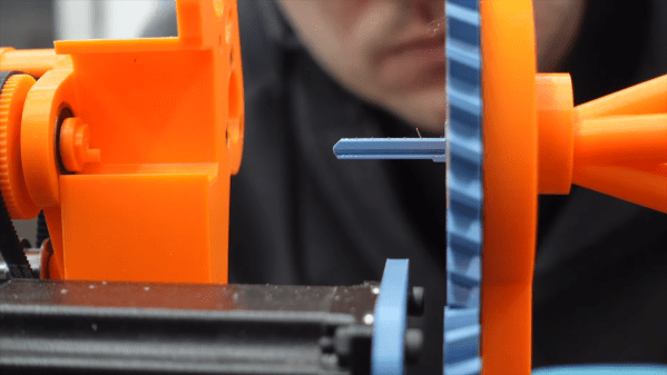
The basics behind [Sparks and Code]’s design are pretty simple. Locks are picked by pushing pins up inside the cylinder until they line up with the shear plane, allowing the cylinder to turn. Normally this is done a pin at a time with a specialized tool and with a slight bit of torque on the cylinder. Here, tough, thin, stiff wires passing through tiny holes in a blade shaped to fit the keyway are used to push all the pins up at once, eliminating the need to keep tension on the cylinder to hold pins in place.
Sounds simple, but in practice, this looks like it was a nightmare. Getting five wires to fit into the keyway and guiding them to each pin wasn’t easy, nor was powering the linear actuators that slide the wires in and out. Applying torque to the lock was a chore too; even though tension isn’t needed to retain picked pins, the cylinder still needs to rotate, which means moving the whole picking assembly. But the biggest problem by far seems to be the fragility of the blade that goes into the keyway. SLA might not be the best choice here; perhaps the blade could be made from two thin pieces of aluminum with channels milled on their faces and then assembled face-to-face.
The robot works, albeit very slowly. This isn’t [Sparks and Code]’s first foray into robot lock picking. His previous version attempted to mimic how a human would pick a lock, so this is really thinking outside the box.
Continue reading “This Robot Picks Locks, If You’re Very Patient”