When The Going Gets Tough, These Wheels Transform To Tracks

When we want to build something to go where wheels could not, the typical solution is to use tracks. But the greater mobility comes with trade-offs: one example being tracked vehicles can’t go as fast as a wheeled counterpart. Information released by DARPA’s ground experimental vehicle technology (GXV-T) program showed what might come out of asking “why can’t we switch to tracks just when we need them?”

This ambitious goal to literally reinvent the wheel was tackled by Carnegie Mellon’s National Robotics Engineering Center. They delivered the “Reconfigurable Wheel-Track” (RWT) that can either roll like a wheel or travel on its tracks. A HMMWV serves as an appropriate demonstration chassis, where two or all four of its wheels were replaced by RWTs. In the video (embedded below) it is seen quickly transforming from one mode to another while moving. An obviously desirable feature that looks challenging to implement. This might not be as dramatic of a transformation as a walking robot that can roll up into a wheel but it has the advantage of being more immediately feasible for human-scale vehicles.

The RWT is not the only terrain mobility project in this DARPA announcement but this specific idea is one we would love to see scaled downed to become a 3D-printable robot module. And though our Hackaday Prize Robotics Module Challenge has already concluded, there are more challenges still to come. The other umbrella of GXV-T is “crew augmentation” giving operators better idea of what’s going around them. The projects there might inspire something you can submit to our upcoming Human-Computer Interface Challenge, check them out!

Continue reading “When The Going Gets Tough, These Wheels Transform To Tracks”

A LIDAR Scanner Build In Glorious Detail

LIDAR is a very exciting technology that is only just now starting to become accessible to the DIY market. Think radar, but with lasers. There’s a few different modules starting to pop up for just a few hundred dollars. But what is one to do with a LIDAR module? Well, [David] decided to build a room scanner with his Garmin LIDAR Lite, and it’s a wonderful sight to behold.

The scanner consists of a rotating platform, which is driven by a stepper motor. The platform then contains a second motor which runs a tilt axis, upon which the LIDAR is mounted. By aiming the LIDAR in various directions, and recording the detected range, it’s possible to build a point cloud representation of the surrounding area.

The build uses a couple of STM32 chips to do motor control and interface with the LIDAR, but where this build really shines is the mechanical side of things. [David] goes into serious detail about the machining of the parts that make up the rotating system, and there’s plenty of cool bits and pieces like slip rings to make it all work. There’s even some home casting going on here! Be warned, though: there’s some rather juicy close-ups of lathes in action, so put the kids to bed before watching this one all the way through.

We love to see a well-executed build, and even more so when we get to watch the intricate details of how it came together. If you’re still looking for some more inspiration, we’ve seen other LIDAR room scanners before, too.

After The Sun Set On San Mateo, LED Takes Over Hackaday’s BAMF Meetup

After this Spring’s Bay Area Maker Faire closed down for Saturday night and kicked everybody out, the fun moved on to O’Neill’s Irish Pub where Hackaday and Tindie held our fifth annual meetup for fellow Maker Faire attendees. How do we find like-minded hackers in a crowded bar? It’s easy: look for tables lit by LEDs and say hello. It was impossible to see everything people had brought, but here are a few interesting samples.

Continue reading “After The Sun Set On San Mateo, LED Takes Over Hackaday’s BAMF Meetup”

Controlling Robotics Visually

The world — and the Hackaday Prize — is filled with educational robots. These are small, wheeled robots loaded up with sensors, actuators, a few motor drivers, and some sort of system that is easy to program. The idea behind these educational robots is to give students an easy-to-use platform to test out code, learn inverse kinematics, and realize odometry is a lot harder than you think it is. Give these kids some time and patience, and you’ll have a fleet of Battlebots at the end of the semester, if the teacher is cool.

But there’s a problem with all educational robots. The programming. For someone just starting out in robotics club, being able to code isn’t a guarantee. You need an easy to use programming interface. This project for the Hackaday Prize gives all students a great visual programming interface. It’s basically like the first generation of Lego Mindstorms, only you don’t need a weird IR tower attached to a serial port.

Of course you can’t program a robot without a board, and this project brings it in spades. The brain for this platform is built on an ARM microcontroller, has Bluetooth, supports up to six DC motors, twelve analog inputs, PWM and serial ports, and all the ports are color-coded for kids who can’t read so good.

This is a visual programming environment, though, and with that, you get a fancy IDE filled with loops that wrap around commands, IO access that’s in easy to read blocks, and control software that gives students a dashboard filled with buttons and odometers and the video feed from the camera. It’s a great Hackaday Prize entry, and an excellent way to introduce kids to robotics.

ROPS Will Be The Board X86 Robot Builders Are Waiting For

If your robot has outgrown a Raspberry Pi and only the raw computing power of an x86 motherboard will suffice, you are likely to encounter a problem with its interfaces. The days of ISA cards are long gone, and a modern PC is not designed to easily talk to noisy robot hardware. Accessible ports such as USB can have interfaces connected to them, but suffer from significant latency in the process.

A solution comes from ROPS, or Robot on a PCI-e Stick, a card that puts an FPGA on a blazing-fast PCI-e card that provides useful real-world interfaces such as CAN and RS485 and a pile of I/O lines as well as an IMU, barometer, and GPS. If you think you may have seen it before then you’d be right, it was one of the first-round winners of the Open Hardware Design Challenge. They’re very much still at the stage of having an FPGA dev board and working out the software so there aren’t any ROPS boards to look at yet, but this is a project that’s going somewhere, and definitely one to watch.

Evolving The 3D Printed Linear Actuator

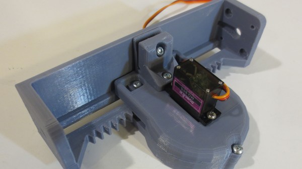
Our open source community invites anyone with an idea to build upon the works of those who came before. Many of us have encountered a need to control linear motion and adapted an inexpensive hobby servo for the task. [Michael Graham] evaluated existing designs and believed he has ideas to advance the state of the art. Our Hackaday Prize judges agreed, placing his 3D Printed Servo Linear Actuator as one of twenty winners of our Robotics Module Challenge.

[Michael]’s actuator follows in the footstep of other designs based on a rack-and-pinion gear such as this one featured on these pages, but he approached the design problem from the perspective of a mechanical engineer. The design incorporated several compliant features to be tolerant of variances between 3D printers (and slicer, and filament, etc.) Improving the odds of a successful print and therefore successful projects. Beginners learning to design for 3D printing (and even some veterans) would find his design tips document well worth the few minutes of reading time.

Another useful feature of his actuator design is the 20mm x 20mm screw mounting system. Visible on either end of the output slider, it allows mixing and matching from a set of accessories to be bolted on this actuator. He is already off and running down this path and is facing the challenge of having too many things to share while keeping them all organized and usable by everyone.

The flexible construction system allows him to realize different ideas within the modular system. He brought one item (a variant of his Mug-O-Matic) to the Hackaday + Tindie Meetup at Bay Area Maker Faire, and we’re sure there will be more. And given the thoughtful design and extensive documentation of his project, we expect to see his linear servos adopted by others and appear in other contexts as well.

This isn’t the only linear actuator we’ve come across. It isn’t even the only winning linear actuator of our Robotics Module Challenge, but the other one is focused on meeting different constraints like compactness. They are different tools for different needs – and all worthy additions to our toolbox of mechanical solutions.

Festo BionicFinWave underwater robot

[Festo]’s Underwater Robot Uses Body-Length Fins

[Festo] have come up with yet another amazing robot, a swimming one this time with an elegant propulsion mechanism. They call it the BionicFinWave. Two fins on either side almost a body-length long create a wave which pushes water backward, making the robot move forward. It’s modeled after such fish as the cuttlefish and the Nile perch.

The BionicFinWave's fin mechanismWhat was their elegant solution for making the fins undulate? Nine lever arms are attached to each fin. Those lever arms are controlled by two crankshafts which extend from the front of the body to the rear, one for each side. A servo motor then turns each crankshaft. Since the crankshafts are independent, that means each fin operates independently. This allows for turning by having one fin move faster than the other. A third motor in the head flexes the body, causing the robot to swim up or down.

There’s also a pressure sensor and an ultrasonic sensor in the head for depth control and avoiding objects and walls. While these allow it to swim autonomously in its acrylic, tubular track, there is wireless communication for recording sensor data. Watch it in the video below as it effortlessly swims around its track.

[Festo] has created a lot of these marvels over the years. We’ve previously covered their bionic hopping kangaroo (we kid you not), their robot ants with circuitry printed on their exoskeleton, and perhaps the most realistic flapping robotic bird ever made.

Continue reading “[Festo]’s Underwater Robot Uses Body-Length Fins”