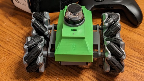
You don’t always need much to build an FPV rig – especially if you’re willing to take advantage of the power of modern smartphones. [joe57005] is showing off his VR FPV build – a fully-printable small Mechanum wheels car chassis, equipped with an ESP32-CAM board serving a 720×720 stream through WiFi. The car uses regular 9g servos to drive each wheel, giving you omnidirectional movement wherever you want to go. An ESP32 CPU and a single low-res camera might not sound like much if you’re aiming for a VR view, and all the ESP32 does is stream the video feed over WebSockets – however, the simplicity is well-compensated for on the frontend. Continue reading “2022 FPV Contest: ESP32-Powered FPV Car Uses Javascript For VR Magic”
Robots Hacks2448 Articles
Robot Rebellion Brings Back BBC Camera Operators
The modern TV news studio is a masterpiece of live video and CGI, as networks vie for the flashiest presentation. BBC News in London is no exception, and embraced the future in 2013 to the extent of replacing its flesh-and-blood camera operators with robotic cameras. On the face of it this made sense; it was cheaper, and newsroom cameras are most likely to record as set range of very similar shots. A decade later they’re to be retired in a victory for humans, as the corporation tires of the stream of viral fails leaving presenters scrambling to catch up.
A media story might seem slim pickings for Hackaday readers, however there’s food for thought in there for the technically minded. It seems the cameras had a set of pre-programmed maneuvers which the production teams could select for their different shots, and it was too easy for the wrong one to be enabled. There’s also a suggestion that the age of the system might have something to do with it, but this is somewhat undermined by their example which we’ve placed below being from when the cameras were only a year old.
Given that a modern TV studio is a tightly controlled space and that detecting the location of the presenter plus whether they are in shot or not should not have been out of reach in 2013, so we’re left curious as to why they haven’t taken this route. Perhaps OpenCV to detect a human, or simply detecting the audio levels on the microphones before committing to a move could do the job. Either way we welcome the camera operators back even if we never see them, though we’ll miss the viral funnies.
Continue reading “Robot Rebellion Brings Back BBC Camera Operators”
3D-Printed Self-Balancing Robot Brings Control Theory To Life
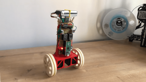
Stabilizing an inverted pendulum is a classic problem in control theory, and if you’ve ever taken a control systems class you might remember seeing pages full of differential equations and bode diagrams just to describe its basic operation. Although this might make such a system seem terribly complicated, actually implementing all of that theory doesn’t have to be difficult at all, as [Limenitis Reducta] demonstrates in his latest project. All you need is a 3D printer, some basic electronic skills and knowledge of Python.
The components needed are a body, two wheels, motors to drive those wheels and some electronics. [Limenitis] demonstrates the design process in the video below (in Turkish, with English subtitles available) in which he draws the entire system in Fusion 360 and then proceeds to manufacture it. The body and wheels are 3D-printed, with rubber bands providing some traction to the wheels which would otherwise have difficulty on slippery surfaces.
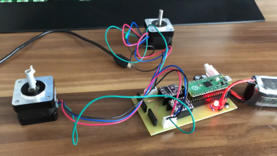
Two stepper motors drive the wheels, controlled by a DRV8825 motor driver, while an MPU-9250 accelerometer and gyroscope unit measures the angle and acceleration of the system. The loop is closed by a Raspberry Pi Pico that implements a PID controller: another control theory classic, in which the proportional, integral and derivative parameters are tuned to adapt the control loop to the physical system in question. External inputs can be provided through a Bluetooth connection, which makes it possible to control the robot from a PC or smartphone and guide it around your living room.
All design files and software are available on [Limenitis]’s GitHub page, and make for an excellent starting point if you want to put some of that control theory into practice. Self-balancing robots are a favourite among robotics hackers, so there’s no shortage of examples if you need some more inspiration before making your own: you can build them from off-the-shelf parts, from bits of wood, or even from a solderless breadboard.
Continue reading “3D-Printed Self-Balancing Robot Brings Control Theory To Life”
Harmonic Vs Cycloidal Show Down
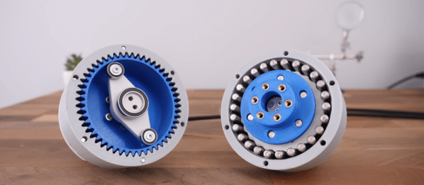
What’s better? Harmonic or cycloidal drive? We aren’t sure, but we know who to ask. [How To Mechatronics] 3D printed both kinds of gearboxes and ran them through several tests. You can see the video of the testing below.
The two gearboxes are the same size, and both have a 25:1 reduction ratio. The design uses the relatively cheap maker version of SolidWorks. Watching the software process is interesting, too. But the real meat of the video is the testing of the two designs.
Your Next Airport Meal May Be Delivered By Robot
Robot delivery has long been touted as a game-changing technology of the future. However, it still hasn’t cracked the big time. Drones still aren’t airdropping packages into our gutters by accident, nor are our pizzas brought to us via self-driving cars.
That’s not to say that able minds aren’t working on the problem. In one case, a group of engineers are working ton a robot that will handle the crucial duty of delivering food to hungry flyers at the airport.
Continue reading “Your Next Airport Meal May Be Delivered By Robot”
2022 FPV Contest: The LOTP Robot Dog
When you think of first person view (FPV) vehicles, aircraft might be what first comes to mind. However, [Limenitis Reducta] has brought a robot dog into the world, and plans to equip it for some FPV adventures.
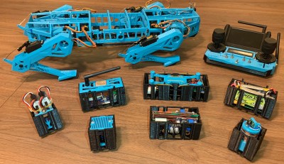
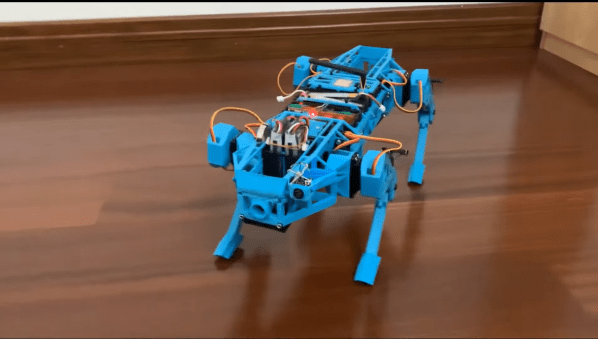
The robot dog itself goes by the name of LOTP, for unspecified reasons, and was designed from the ground up in Fusion 360. A Teensy 3.5 is charged with running the show, managing control inputs and outputting the requisite instructions to the motor controllers to manage the walk cycle. Movement are issued via a custom RC controller. Thanks to an onboard IMU, the robotic platform is able to walk effectively and maintain its balance even on a sloping or moving platform.
[Limenitis] has built the robot with a modular platform to support different duties. Equitable modules include a sensor for detecting dangerous gases, a drone launching platform, and a lidar module. There’s also a provision for a camera which sends live video to the remote controller. [Limenitis] has that implemented with what appears to be a regular drone FPV camera, a straightforward way to get the job done.
It’s a fun build that looks ready to scamper around on adventures outside. Doing so with an FPV camera certainly looks fun, and we’ve seen similar gear equipped on other robot dogs, too.
Mini Cheetah Clone Teardown, By None Other Than Original Designer
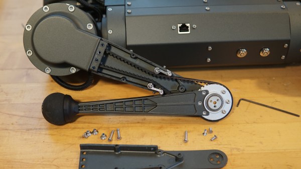
[Ben Katz] designed the original MIT Mini Cheetah robot, which easily captured attention and imagination with its decidedly un-robotic movements and backflips. Not long after [Ben]’s masters thesis went online, clones of the actuators started to show up at overseas sellers, and a few months after that, clones of the whole robot. [Ben] recently had the opportunity to disassemble just such a clone by Dogotix and see what was inside.
Amusingly, one of the first things he noticed is that the “feet” are still just off-the-shelf squash balls, same as his original mini cheetah design. As for the rest of the leg, inside is a belt that goes past some tensioners, connecting the knee joint to an actuator in the shoulder.
As one may expect, these parts are subject to a fair bit of stress, so they have to be sturdy. This design allows for slender yet strong legs without putting an actuator in the knee joint, and you may recall we’ve seen a similar robot gain the ability to stand with the addition of a rigid brace.
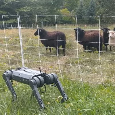
It’s interesting to read [Ben]’s thoughts as he disassembles and photographs the unit, and you’ll have to read his post to catch them all. But in the meantime, why not take a moment to see how a neighbor’s curious sheep react to the robot in the video embedded below? The robot botches a backflip due to a low battery, but the sheep seem suitably impressed anyway.
Continue reading “Mini Cheetah Clone Teardown, By None Other Than Original Designer”

