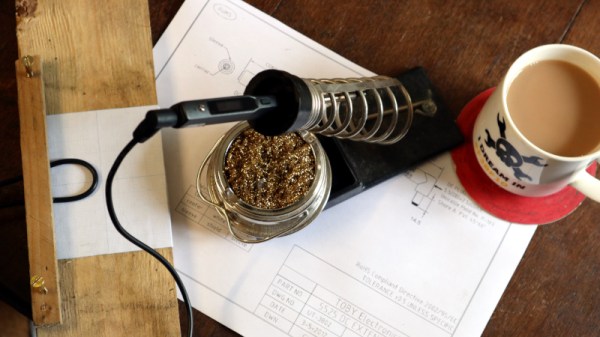
Vernier Calipers And Micrometer Screw Gauges, Measuring Without Compromise

I needed a temperature controller module recently, so off I went to Banggood to order one. As one does I found myself browsing, one thing led to another, and I bought a micrometer screw gauge. While micrometers are pretty expensive devices, reflecting their high precision engineering and construction, this micrometer cost me only about £8, or just under $10, definitely in the spirit of our long-running series of reviewing very cheap tools in search of a diamond in the rough. But perhaps more importantly, this is also the cue for an examination of high precision dimensional measurement. So I’ve assembled a collection of micrometers and vernier calipers of varying quality, and it’s time to dive in and measure some very small things.

Some of you will be metrology enthusiasts with an array of the finest devices available, but I am guessing that many of you will not. The ubiquitous precision measurement device in our community appears to be the digital caliper, a sliding clamp with an LCD display, an instrument that can be had in its most basic form for a very small outlay indeed. For the purposes of this piece though we’re not looking at digital devices but their analogue precursors. If you want a feel for metrology and you’d like some of those heritage tools that parents pass onto their kids then it’s time to learn something about the vernier caliper and the micrometer. Continue reading “Vernier Calipers And Micrometer Screw Gauges, Measuring Without Compromise”

Adjustable Jig Eases PCB Stencil Alignment Process

PCB stencils make application of solder paste a snap, but there’s a long, fussy way to go before the paste goes on. You’ve got to come up with some way to accurately align the stencil over the board, which more often than not involves a jury-rigged setup using tape and old PCBs, along with a fair amount of finesse and a dollop of luck.

Luckily, [Valera Perinski] has come up with a better way to deal with stencils. The Stencil Printer is a flexible, adjustable alignment jig that reduces the amount of tedious adjustment needed to get things just so. The jig is built mostly from aluminum extrusions and 3D-printed parts, along with a bunch of off-the-shelf hardware. The mechanism has a hinged frame that holds the stencil in a fixed position above a platen, upon which rests the target PCB. The board is held in place by clamps that ride on threaded rods; with the stencil flipped down over the board, the user can finely adjust the relative positions of the board and the stencil, resulting in perfect alignment. The video below is mainly a construction montage, but if you skip to about the 29:00 mark, you’ll see the jig put through its paces.

Granted, such a tool is a lot more work than tape and spare PCBs, but if you do a lot of SMD work, it may be worth the effort. It’s certainly less effort than a solder-paste dispensing robot.

Continue reading “Adjustable Jig Eases PCB Stencil Alignment Process”

Testing Hardware With ASCII Waveforms

Testing software is — sometimes — easier than testing hardware. After all, you can always create test files and even fake user input before monitoring outputs using common tools. Hardware though, is a bit different. Sometimes it is hard to visualize exactly what’s happening. [Andrew Ray’s] answer? Produce simulated waveforms using ASCII text.

The process uses some custom tools written in OCaml, but the code is available for you on GitHub. The tool, called Hardcaml, allows you to write test benches for hardware — not a new idea for FPGA developers. The output, however, is an ASCII text waveform and common software development tools can check that waveform against the expected output.

Continue reading “Testing Hardware With ASCII Waveforms”

A DIY Electronic Load With A Twist

If you’re testing a power supply or battery pack, an electronic load is a nice tool to have. By watching the voltage as you crank up the resistance, you can verify the unit’s real-world capabilities quickly and easily. But [Xavier Bourlot] wanted a bit more information than is generally afforded by these devices, so he came up with his own scratch built load that can measure the voltage at multiple points in the circuit.

Now at first glance, it might not be obvious why you’d want such a capability. But [Xavier] is looking to do something very specific with this device: analyze the efficiency of DC-DC converters. The idea is that if the electronic load can measure the voltage on both sides of the converter, it can calculate what kind of losses are being incurred.

Could you do this with a multimeter and a traditional electronic load? Sure. But if it’s the kind of thing you’ll be doing a lot of, it’s not hard to see why this method would be preferable.

But even if you ignore the converter analysis capabilities, this looks to be a very useful device to have around the lab. [Xavier] says it can sink more than 5 amps, and handle an input voltage as high as 100 volts. Powered by an ATmega328P, the load is also fully programmable and even features an I2C expansion port that you can use to hang additional hardware or sensors on. The stock firmware is already quite capable, and the list of future enhancements has some very interesting entries such as the ability to log data over serial or to a SD card.

We’ve seen a number of programmable electronic load projects over the years, ranging from Arduino shields to VFD equipped units that would be the pride of any hacker’s bench.

Vacuum Dust Collection With Self-Powered Relays

Like many people with multiple woodworking tools, [Will Stone] wanted to create a centralized dust collection system. But he quickly found that the devil was in the details, as he struggled to find an economic way to automatically kick on the vacuum when one of the tools started up. His final solution might be one of the most elegant, and surely the cheapest, we’ve ever come across.

As with other DIY systems we’ve seen over the years, [Will] is using a simple inductive current sensor to detect when AC power is being drawn by one of his tools. But where the similarity stops is that there’s nothing so pedestrian as a microcontroller reading the output of the sensor. He realized that when the coils in the sensor were energized they were putting out about 7 volts AC, which should be more than enough to trigger a relay.

So he threw together a rectifier circuit on a piece of perfboard, using four LEDs in true hacker style. With the addition of a capacitor to smooth out the voltage, this little circuit is able to trip the 40 amp solid state relay controlling power to the vacuum using nothing more than the energy harvested from the sensor’s coil.

Using a current sensor is great when the tools are close enough to all be plugged into the same line, but that doesn’t help the folks with cordless tools or supersized shops. In that case, you might need to look into a sound-activated system.

Homebrew Coil Winder Makes Toroids A Snap To Wind

Anyone who has ever wound a toroidal coil by hand can tell you that it’s not exactly a fun job. Even with the kinds of coils used in chokes and transformers for ham radio, which generally have relatively few windings, passing all that wire through the toroid time after time is a pain. And woe unto anyone who guesses wrong on how much wire the job will take.

To solve those problems, [Sandeep] came up with this clever and effective toroid winder. The idea is to pass a small spool of magnet wire through the toroid’s core while simultaneously rotating the toroid to spread the windings out as evenly as possible. That obviously requires a winding ring that can be opened up to allow the toroid form to be inserted; [Sandeep] chose to make his winding ring out of plywood with a slit in it. Carrying the wire spool, the winding ring rotates on a C-shaped fixture that brackets the toroid, which itself rotates under stepper motor control on a trio of rollers. An Arduino controls the rotation of both motors, controlling the number of windings and their spread on the form. lacking a ferrite core for testing, [Sandeep] used a plywood ring as a stand-in, but the results are satisfying enough to make any manual coil-winder envious.

We love tools like this that make a boring job a snap. Whether it’s cutting wires for wiring harnesses or winding guitar pickups, tools like these are well worth the time spent to build them. But we suppose when it comes to toroid winding, one could always cheat.

Continue reading “Homebrew Coil Winder Makes Toroids A Snap To Wind”

CNC Scroll Saw Makes Promising First Cuts

When we talk about CNC machines, we almost invariably mean a computer controlled router. Naturally you can do other forms of automated cutting, say using a laser or a water jet, but what about adding computer control to other types of saws? [Andrew Consroe] recently put together a postmortem video about this experimental CNC scroll saw. While he never quite got it working reliably, we think his approach is absolutely fascinating and hope this isn’t the last we see of the idea.

Those who’ve used a scroll saw in the past might immediately see the challenge of this build: while a router bit or laser beam can cut in any direction, a scroll saw blade can only cut in one. If you tried to make a sharp turn on a scroll saw, you’ll just snap the fragile blade right off. To work around this limitation, [Andrew] came up with the brilliant rotary table that can be seen in the video after the break.

By combining motion of the gantry with table rotation, he’s able to keep the blade from ever making too tight a turn. Or at least, that’s the theory. While the machine works well enough with a marker mounted in place of the blade, [Andrew] says he never got it to the point it could reliably make cuts. It sounds like positioning errors would compound until the machine ended up moving the work piece in such a way that would snap the blade. Still, the concept definitely works; towards the end of the video he shows off a couple of pieces that were successfully cut on his machine before it threw the blade.

While we’ve actually seen DIY scroll saws in the past, this is the first computer controlled one to ever grace the pages of Hackaday. While some will no doubt argue that there’s no sense building one of these now that laser cutters have reached affordable prices, we absolutely love this design and how much thought went into it. At the very least, we figure this it the beefiest doodle-drawing robot ever constructed. Continue reading “CNC Scroll Saw Makes Promising First Cuts”