Whether or not you personally agree with all the ideals of the Free Software Foundation (FSF), you’ve got to give them credit: they don’t mess around. They started by laying the groundwork for a free and open source operating system, then once that dream was realized, started pushing the idea of replacing proprietary BIOS firmware with an open alternative such as Libreboot. But apparently, even that’s not enough, as there’s still more freedom to be had. We’re playing 4D Libre Chess now, folks.
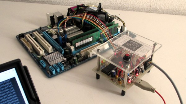
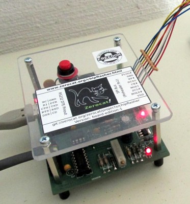 To flash your libre boot firmware on your libre OS running computer without any proprietary funny business, you’re going to need a libre chip programmer. Luckily, the FSF has just awarded the Zerocat Chipflasher their “Respects Your Freedom” certification, meaning every element of the product is released under a free license for your hacking enjoyment. According to the FSF, this is a major milestone towards their goal of providing users a truly free and open source computer, from the browser all the way down to the BIOS.
Of course, you don’t need to be Richard Stallman to appreciate a fully open chip programmer. With the software, wiring diagrams, and PCB files available on the Chipflasher’s website, the project is an excellent educational reference. Is also means that with a clone the Chipflasher’s Git repository, you’re well on the way to spinning up your own build of the device.
Given the roughly $350 USD price tag on the first generation Zerocat Chipflasher, it seems fairly likely we’ll be seeing some DIY builds of this device before too long. Not that we want to deprive Zerocat commercial success for this very neat piece of gear, but for many it’s a mighty steep price; even if you do get all the Freedoms.
It may use a device of slightly more nebulous morality than the Zerocat Chipflasher, but our own [Bryan Cockfield] documented the saga of getting Libreboot installed on a Thinkpad X200 if you’d like to know more about the high stakes world of BIOS replacement. Whatever it takes to get that Intel Management Engine off your penguin-powered box.