Cheap Caliper Hack Keeps ‘Em Running Longer

Many a hacker is a fan of the cheapest calipers on the market. Manufactured in China and priced low enough that they’re virtually disposable, they get a lot of jobs done in the world where clinical accuracy isn’t required. However, their batteries often die when left in a drawer for a long time. [Ben] was sick of that, and got to hacking.

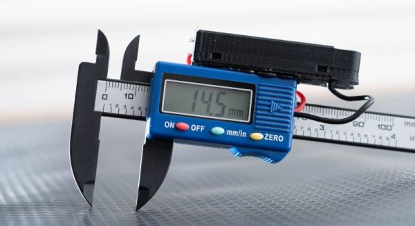
The result was a quick-and-dirty mod that allows the calipers to be powered by a AAA battery. The average AAA cell has 5-10 times the capacity of the typical LR44 coin cells used in these devices.

[Ben] whipped this up with an eye to making it work rather than making it nice, so there are some shortcuts taken. The battery housing was 3D-printed on the lowest-quality settings that were viable, and it’s held to the calipers with hot glue. Similarly, bare wire ends were used instead of proper contacts, taking advantage of the battery being crammed in to make a good connection.

It’s a hack that will likely save [Ben] much frustration, as he’ll now rarely open his drawer to find his calipers dead. However, one [Pete Prodoehl] suggests another useful trick: store the calipers in the closed position with the lock screw tight to save them turning themselves on accidentally.

Whichever way you go, you’ve hopefully learned something today that will keep your cheap calipers working when you need them. Next, you might consider hacking them to capture data, too.

Oscilloscope Clocks: Now In Color!

Ordinarily, when we hear the words “clock” and “oscilloscope” in the same sentence we conjure images of measuring a stable, repeating square wave that acts as the heartbeat of a system. Of course, that’s not the only meaning– there’s a much more fun and less useful one: using an oscilloscope to display the time.

That’s what [Wolfgang Friedrich] set out to do when he cobbled some protoboard, probes, and an FPGA into the Multi Color Oscilloscope Clock. Each digit on the clock is treated like a seven-segment display, made up of three horizontal bars and four vertical bars. The horizontal bars are generated by constant voltage at different levels, and the vertical bars are generated by quickly switching between two voltages. [Wolfgang] decided to use an R-2R resistor ladder DAC to create the appropriate analog signals from the FPGA’s digital outputs. For bonus points, each set of digits (hours, minutes, and seconds) are output concurrently through separate channels, so they can be displayed in different colors on the screen of his four-channel scope (the fourth channel is used for the points between numbers).

Misusing oscilloscopes in the name of fun has become a time-honored tradition– from Tennis for Two back in 1958 (which later became the beloved Pong) to the plethora of analog o-scope clocks we’ve seen, it’s clear that hackers just can’t get enough of the unique vector display style that a scope can provide. We love [Wolfgang]’s idea of using the scope’s channels to create a multi-color display, and we’re left wondering what kind of wacky waveforms we’ll be seeing next.

Big homemade lathe

Heavy Metal Lathe Build Doesn’t Spare The Steel

It’s common wisdom that the lathe is the essential machine tool, and the only one that can make copies of itself. While we won’t argue the primacy of the lathe in the machine shop, this scratch-built, heavy-duty lathe gives the lie to the latter argument — almost.

We’re used to seeing homebrew lathes, of course, and we’ve featured more than a few of them before. But two things make [Jornt]’s build stand out: how few specialized tools were needed to build it, and the sheer size and bulk of the finished product. Where most homebrew lathes tend to be the bench top variety and feature cast aluminum parts, [Jornt] went with steel for his build, and a lot of it. The base and bed of the machine are welded from scrap steel I-beams, and the ways are made from angle iron that has been ground flat with a clever jig to hold an angle grinder. The angle grinder plays a prominent role in the build, as do simple tools like a hand drill, files, and a welder — and yes, the unfinished lathe itself, which was used to bore out the bearing blocks for the headstock.

The completed lathe, powered by a treadmill motor in a way that [Jeremy Fielding] would no doubt endorse, comes in at a beefy 450 kg. It honestly looks like something you could buy from a catalog, and has most of the features of commercial machines. One thing we’d love to see on this lathe is the electronic lead screw that [James Clough] developed for his off-the-shelf lathe.

Continue reading “Heavy Metal Lathe Build Doesn’t Spare The Steel”

Klein Hidden Bolt and Tool

Tricky Screw Heads Have Disappearing Slots

Perhaps you’ve seen them, demonstrations of a machined piece of metal that upon further inspection is actually two pieces machined so perfectly that they appear as one. With extremely tight tolerances, it’s not possible to determine where one piece of metal ends and another begins — that is, until the secret is revealed. Inspired by such pieces of art, [Andrew Klein] sought to put this high level of machine work to practical use. And so it was that his as-yet-unnamed Screw With No Slot came to be.

Klein Hidden Bolt depressed by brass rod
A brass rod pushes down to reveal the keyed center section.

The screw’s disc-like appearance looks as if it’s a metal trim piece to cover a bolt hole. But in the video below [Andrew] shows us the trick, pushing a brass rod into the middle of the disc to reveal the hidden three-point slot. The center of the disk is actually a separate bit of finely machined metal that is spring loaded to stay flush. A specially designed wrench keys into the rounded concave triangle shape cut into the face.

The wrench is made with brass to avoid marring the precision surface. It uses three magnets to hold tight to the screw’s 410 magnetic stainless steel. [Andrew] didn’t spill the beans on how this was done, but we haven’t seen any process other than electrical discharge machining (EDM) that can achieve this level of mating precision. If that topic is new to you, we recommend checking out [Ben Krasnow’s] lab experiments on the topic.

We can’t help but be taken in by the beauty of the fastener, and it immediately sent our imaginations into a National Treasure induced dream-like state. [Andrew Klein] has yet to name this fastener, and he’s soliciting ideas for names in the video below the break. If you have such an idea, you can comment on his video. He’s also exploring the viability of the as-yet-named fastener as a commercial product for high end furniture builders.

This is not the first time we’ve featured [Andrew Klein]’s work. His previous featured projects include a custom sawblade for perfectly foldable joints and an unveiling of the magnetic magic behind switchable permanent magnets. Be sure to submit the neat hacks, builds, and inspiring projects that you come across to our Tip Line!

Continue reading “Tricky Screw Heads Have Disappearing Slots”

A sandbox for ergonomic keyboard makers.

Dactyl Chimera Leaves The Learning Out Of The Curve

Have you been wanting to build your own keyboard, ergonomic or otherwise, but are hesitant to spend all that time and filament on something that may not be a good fit for your hands? Glad as we are that the dactyl is open-source, to get in there and really mess around with it requires intimate knowledge of either OpenSCAD or Clojure.

Well, not anymore. [WolfIcefang]’s dactyl chimera is an ergo sandbox, a test bench for column curvature, stagger, and height that should keep you from having to iterate all day and night. It was designed in FreeCAD and has three parts — the rack, the tenting foot, and the arches. The rack acts like a bottom plate and has slots for holding the columns (arches) in place. Underneath that is the tenting foot, which changes the lateral inclination. Thirdly are the arches, the business part where the switches go.

[WolfIcefang] says it’s sturdy but not portable, and for some reason feels the need to apologize for the looks. We think it’s beautiful, but then again are easily captivated by such practicality. It’s not quite a keyboard yet, as [WolfIcefang] has neither wired it up nor burned in any firmware. This is still in the early stages, and [WolfIcefang] wants to open it up to collaborators. Plans for the future include interchangeable thumb clusters and a complete build guide.

Even if you aren’t that fluent in OpenSCAD, you’ll have fun messing around on the keycap modeling playground.

Via r/ErgoMechKeyboards

Chip Tester Knows If Your Old Chips Are Working

[Noel’s Retro Lab] has looked at retro chip testers before, but in a recent video you can see below he’s looking at the Chip Tester Pro, a preassembled chip tester for vintage chips, especially those used in Commodore computers. The device looks good on the surface with a form factor like a calculator or cell phone, an LCD display, and a 48 pin ZIF socket.

The user interface is pretty simple. A rotary encoder and a big red button are about it. However, there are also some headers where you have to use jumpers to wire signals to the chip. The firmware gives you specific directions, but it is reminiscent of programming old punchcard machines with jumper wires. Luckily, it looks like you only route the power to the device so you don’t have many wires to connect (usually two or three).

Continue reading “Chip Tester Knows If Your Old Chips Are Working”

3D Printable Scope Probe Adapts To Your Needs

If there’s one this we electronics engineers are precious about, it’s our test gear. The instruments themselves can be obscenely expensive, since all that R&D effort needs to be paid back over a much smaller user base compared to say a DVD player. The test probes themselves can often come with an eye-watering price tag as well. Take the oscilloscope probe, pretty much everyone who tinkers with hardware will be familiar with. It’s great for poking around, looking desperately for inspiration when you’re getting stuck in with some debug, but you’ve only got two hands, and that doesn’t leave any spare for button pushing.

Hands-free probing solutions exist, but they can be pricey, flimsy or just a pain to use. Sometimes you just want to solder a wire and leave the probe attached, hoping the grounding lead doesn’t fall off and short something. We’ve seen many solutions to this, so here’s yet another one you can 3D print yourself, so it’s almost free to make.

The two-part 3D printed assembly embeds a pair of wires with a Molex 0008500113 sprung terminal on one end, which can be terminated with your choice of pins, headers or just a pair of plain ‘ol wires. Once you’ve dropped your wiring of choice inside, simply glue the halves with a little cyanoacrylate and you’re good to go. Designed around the Siglent 200MHz PP215 specifically, it is likely compatible with many other brands. Thingiverse only has STL files (sigh!) so it may be tricky to adapt it to your exact probe dimensions, but the idea is good at least.

There is no shortage of electronics probing solutions out there, and boy have we covered a few over the years, here’s a low-cost current probe, an Open Source 2 GHz scope probe, and if you want to get really hacky, look no further for inspiration than the 2019 Hackaday SuperCon SMD Challenge.

Thanks [daniel] for the tip!