It’s hardly a secret that getting into a serious electronics habit can be detrimental to your bank account. A professional grade lab is simply unobtainable for many a tinkerer, and even mid-range hardware can set you back considerably. Which is why many folks just starting out will attempt to salvage or build as much of their equipment as possible. It might not always be pretty, but it’ll get the job done.
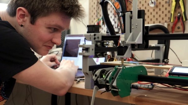
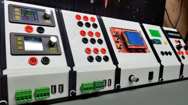
But this project by [Chrismettal] could end up completely reinventing the home electronic workspace. Using 3D printed frames, low-cost components, and a sprinkling of custom PCBs, this modular electronics workbench has all the bells and whistles an aspiring hardware hacker could need. As an added bonus, it looks like something that came off the International Space Station.
This is one of those projects that simply can’t be done justice in a few paragraphs. If you’ve ever wanted to put together a dedicated electronics workbench but were put off by the cost of individual components, read though the fantastic documentation [Chrismettal] has prepared for the EleLab_v2. Is it all top-of-the-line hardware? No, of course not. But it’s more than suitable for the kind of work people in this community usually find themselves involved in on a weekend.
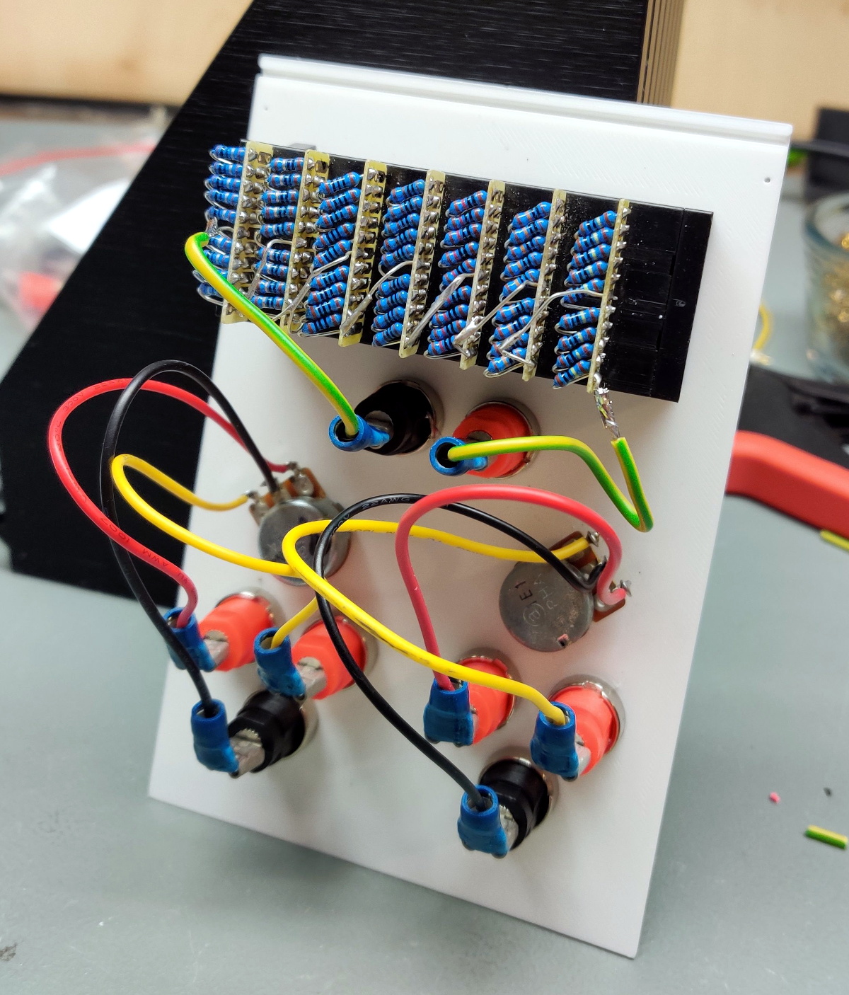
So what’s included? Naturally [Chrismettal] has created a power supply module, in both variable and fixed flavors. But there’s also a module for a resistor substitution, a component tester, and even a digital storage oscilloscope. You can mix and match the modules suit your needs, and if you want to create entirely new ones, the FreeCAD sources are available to get you started.
We’ve seen low-cost power supply modules before, and naturally we’re no strangers to cheap DSO kits. But this project wraps those devices and gadgets up into a form factor that anyone would be happy to have on their bench. We’re exceptionally interested in seeing new modules developed for the EleLab_v2, and doubt this is the last time you’ll see this impressive project grace these pages.
[Thanks to BrunoC for the tip.]