Making a natural fiber like wool into something useful like a sweater involves a lot of steps. We might be familiar with shearing the sheep, spinning the wool into yarn, or knitting and weaving, but between shearing and spinning there’s another unfamiliar process you’ll have to go through. Known as carding, it helps align the fibers so they are able to be spun, and of course it requires either an expensive tool, or one you build on your own.
This drum carder is exactly what it sounds like. It uses two drums covered in a metal mesh, spinning at different speeds, which pull the fibers into an orderly shape. Small drum carders like this can run around $600 but with some quality wood and a lathe you can easily make one for a fraction. Making the series of drums is fairly straightforward with a lathe, and from there you need to make sure they are connected with a quality belt or chain and then covered in the appropriate metal mesh.
[kris] notes in the reddit comments section that he’d like for a second version to spin a little faster and be a little more durable, but this is a great working carder nonetheless. From there you’ll want to move on to spinning the wool into yarn, which you can do with either a wheel or an electric motor.
A remote Ethernet device needs two things: power and Ethernet. You might think that this also means two cables, a beefy one to carry the current needed to run the thing, and thin little twisted pairs for the data. But no!
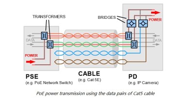
Power over Ethernet (PoE) allows you to transmit power and data over to network devices. It does this through a twisted pair Ethernet cabling, which allows a single cable to drive the two connections. The main advantage of using PoE as opposed to having separate lines for power and data is to simplify the process of installation – there’s fewer cables to keep track of and purchase. For smaller offices, the hassle of having to wire new circuits or a transformer for converted AC to DC can be annoying.
PoE can also be an advantage in cases where power is not easily accessible or where additional wiring simply is not an option. Ethernet cables are often run in the ceiling, while power runs near the floor. Furthermore, PoE is protected from overload, short circuiting, and delivers power safely. No additional power supplies are necessary since the power is supplied centrally, and scaling the power delivery becomes a lot easier.
Devices Using PoE
[via PowerOverEthernet.com]VoIP phones are becoming increasingly prevalent as offices are opting to provide power for phones from a central supply rather than hosting smaller power supplies to supply separate phones. Smart cameras – or IP cameras – already use Ethernet to deliver video data, so using PoE simplifies the installation process. Wireless access points can be easily connected to Ethernet through a main router, which is more convenient than seeking out separate power supplies.
Other devices that use PoE include RFID readers, IPTV decoders, access control systems, and occasionally even wall clocks. If it already uses Ethernet, and it doesn’t draw too much power, it’s a good candidate for PoE.
On the supply side, given that the majority of devices that use PoE are in some form networking devices, it makes sense that the main device to provide power to a PoE system would be the Ethernet switch. Another option is to use a PoE injector, which works with non-PoE switches to ensure that the device is able to receive power from another source than the switch.
How it Works
Historically, PoE was implemented by simply hooking extra lines up to a DC power supply. Early power injectors did not provide any intelligent protocol, simply injecting power into a system. The most common method was to power a pair of wires not utilized by 100Base-TX Ethernet. This could easily destroy devices not designed to accept power, however. The IEEE 802.3 working group started their first official PoE project in 1999, titled the IEE 802.3af.
[via Fiber Optic Communication]This standard delivered up to 13 W to a powered device, utilizing two of the four twisted pairs in Ethernet cabling. This was adequate power for VoIP phones, IP cameras, door access control units, and other devices. In 2009, the IEEE 802.3 working group released the second PoE standard, IEEE 802.3at. This added a power class that could deliver up to 25.5 W, allowing for pan and tilt cameras to use the technology.
While further standards haven’t been released, proprietary technologies have used the PoE term to describe their methods of power delivery. A new project from the IEEE 802.3 working group was the 2018 released IEEE 802.3bt standard that utilizes all four twisted pairs to deliver up to 71 W to a powered device.
But this power comes at a cost: Ethernet cables simply don’t have the conductive cross-section that power cables do, and resistive losses are higher. Because power loss in a cable is proportional to the squared current, PoE systems minimize the current by using higher voltages, from 40 V to 60 V, which is then converted down in the receiving device. Even so, PoE specs allow for 15% power loss in the cable itself. For instance, your 12 W remote device might draw 14 W at the wall, with the remaining 2 W heating up your crawlspace. The proposed 70 W IEEE 802.3bt standard can put as much as 30 W of heat into the wires.
The bigger problem is typically insufficient power. The 802.4af PoE standard maximum power output is below 15.4 W (13 W delivered), which is enough to provide power for most networking devices. For higher power consumption devices, such as network PTZ cameras, this isn’t the case.
Although maximum power supply is specified in the standards, having a supply that supplied more power is necessary will not affect the performance of the device. The device will draw as much current as necessary to operate, so there is no risk of overload, just hot wires.
So PoE isn’t without its tradeoffs. Nevertheless, there’s certainly a lot of advantages to accepting PoE for devices, and of course we welcome a world with fewer wires. It’s fantastic for routers, phones, and their friends. But when your power-hungry devices are keeping you warm at night, it’s probably time to plug them into the wall.
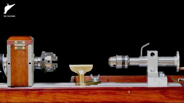
It’s a treadle lathe! No, it’s a power lathe! It’s a wood lathe! No, it’s a metal lathe! Actually, [Uri Tuchman]’s homebrew lathe is all of the above, and it looks pretty snazzy too.
To say that [Uri]’s creations are quirky is a bit of an understatement – birds, crustaceans, hands, and feet all appear repeatedly as motifs in his work – but there’s no overstating his commitment to craftsmanship. [Uri] turns wood and metal into wonderful tools, nonsense machines, and finely detailed instruments, like this exquisitely engraved astrolabe we featured a while back.
[Uri] mostly works with hand tools, supplemented by an old Singer treadle-powered sewing machine that he turned into a scroll saw. The video below shows how he added a small scratch-built lathe to the treadle base. His first pass at a headstock, using pillow blocks for bearings, didn’t work as well as he wanted, so he built a new headstock around off-the-shelf lathe parts. The aluminum extrusion bed holds the headstock, tailstock, and a custom-built tool rest of heavy brass, all of which look great alongside the rich wood accent pieces and base. And for those times when his feet are tired, he added a surplus electric motor to turn the spindle. We especially like the two settings on the motor speed control: “0” and “>0”. Classic [Uri].
If you are building a home shop, it is common to try to get the cheapest gear you can possibly get. However, professionals often look at TCO or total cost of ownership. Buying a cheap car, for example, can cost more in the long run compared to buying an expensive car that requires less maintenance. Most consumers will nod sagely and think of ink jet printers. That $20 printer with the $80 cartridges might not be such a deal after all. [JohnAudioTech] bought a few cheap multimeters and now has problems with each of them. Maybe that $120 meter isn’t such a bad deal, after all.
The problems he’s seen are the same ones we’ve all seen: noisy selector switches, suspect display readings, and worn off lettering. You can see the whole story in the video below.
Brushless motors and lithium batteries were a revolution for remote control aircraft. No longer would nitro engines rule the roost, as flying became far cheaper and more accessible almost overnight. The same technology has also found its way into power tools, leading to [Peter Sripol] deciding to build a powerdrill into a flying aircraft in this video, embedded below.
An unmodified DeWalt drill is the heart of the build, serving as the propulsion unit of the craft. A servo is used to actuate the drill’s trigger to serve as the throttle. As power drills are geared down significantly compared to a typical hobby brushless motor, it was necessary to use a much larger prop than would be usual. This was custom machined out of wood with the help of [William Osman], and despite some mishaps, came out (mostly) in one piece. The airframe consists of foam wings with poplar spars, and an aluminium extrusion serves as the tail boom. A few 3D printed parts then tie everything together.
Despite the weight of the drill, the hacked-together craft is able to fly quite easily. The large wings and propeller help to make up for the shortcomings of the powertrain. Unfortunately, there wasn’t quite enough surplus lift to carry a payload of smartphones to capture in-flight footage, but overall the project could be considered a resounding success.
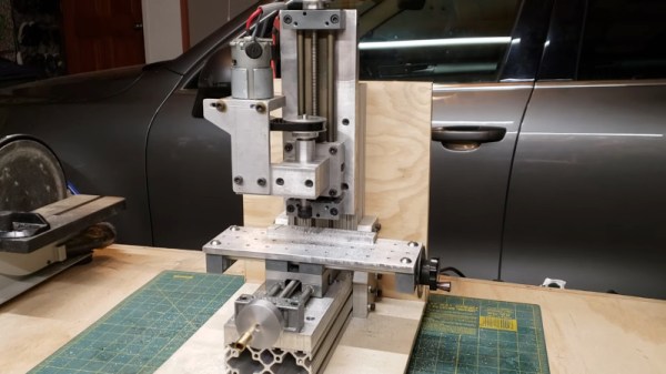
Hanging around the machining community online, you’d be more than familiar with clapped out Bridgeport mills, which are practically a meme at this point. But mills come in all shapes and sizes, from the stout old iron from the days of yore, to smaller, compact builds. [Honus] decided to build the latter, and shared the details of the project.
The aim of [Honus’s] build is to create a small benchtop mill, capable of handling the smaller tasks. The frame of the mill is built out of 80/20 extrusion, with plenty of aluminium plate to go along with it. Igus linear slides handle the X, Y and Z axes. An old brushed Makita drill motor serves as the spindle drive, controlled by an old R/C speed controller hooked up to an Arduino. [Honus] then fabbed up various bits and pieces as neccessary to bring it all together.
The mill is neat and tidy, and looks to do a good job machining aluminium. We imagine it should prove highly useful in [Honus’s] workshop. If you’re contemplating getting yourself some desk-sized tools, perhaps consider an engraver as well! Video after the break.
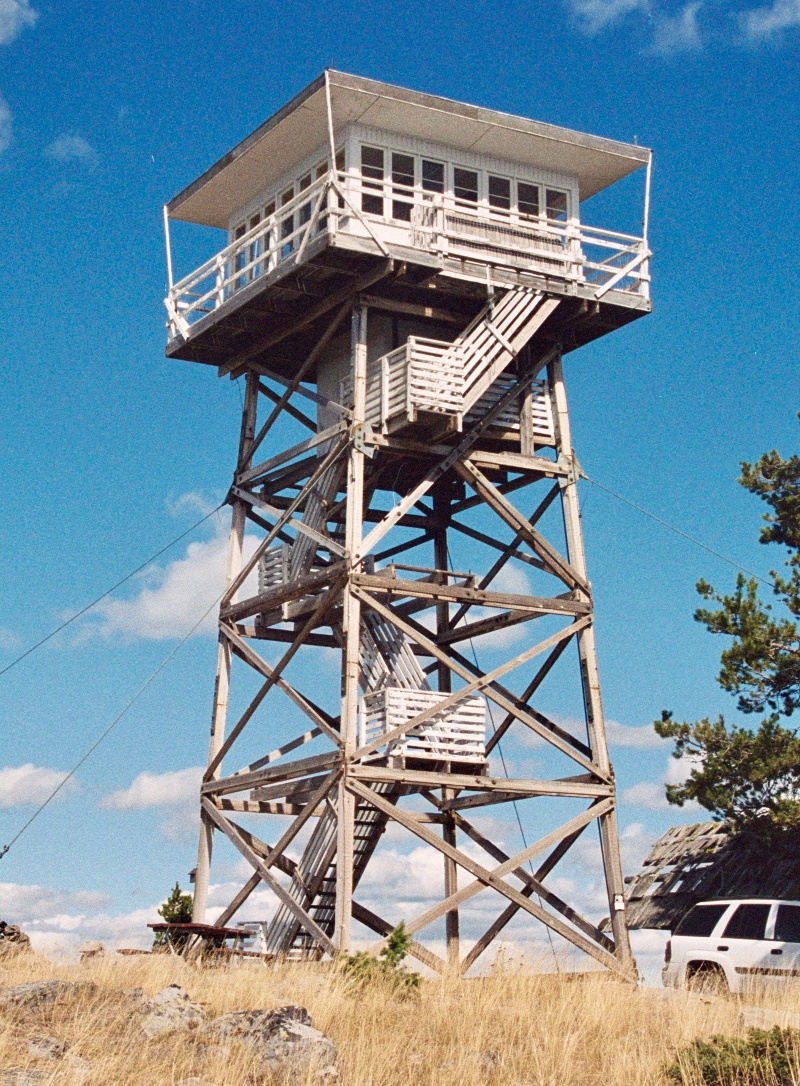
For more than a century, the United States Forest Service has employed men and women to monitor vast swaths of wilderness from isolated lookout towers. Armed with little more than a pair of binoculars and a map, these lookouts served as an early warning system for combating wildfires. Eventually the towers would be equipped with radios, and later still a cellular or satellite connection to the Internet, but beyond that the job of fire lookout has changed little since the 1900s.
Like the lighthouse keepers of old, there’s a certain romance surrounding the fire lookouts. Sitting alone in their tower, the majority of their time is spent looking at a horizon they’ve memorized over years or even decades, carefully watching for the slightest whiff of smoke. The isolation has been a prison for some, and a paradise for others. Author Jack Kerouac spent the summer of 1956 in a lookout tower on Desolation Peak in Washington state, an experience which he wrote about in several works including Desolation Angels.
But slowly, in a change completely imperceptible to the public, the era of the fire lookouts has been drawing to a close. As technology improves, the idea of perching a human on top of a tall tower for months on end seems increasingly archaic. Many are staunchly opposed to the idea of automation replacing human workers, but in the case of the fire lookouts, it’s difficult to argue against it. Computer vision offers an unwavering eye that can detect even the smallest column of smoke amongst acres of woodland, while drones equipped with GPS can pinpoint its location and make on-site assessments without risk to human life.
At one point, the United States Forest Service operated more than 5,000 permanent fire lookout towers, but today that number has dwindled into the hundreds. As this niche job fades even farther into obscurity, let’s take a look at the fire lookout’s most famous tool, and the modern technology poised to replace it.