DIY Adjustable Wrench? Nuts!

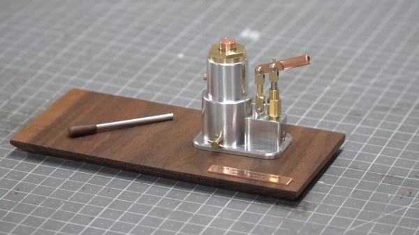
What do you do if you want a tiny little adjustable wrench? If you’re [my mechanics] you build your own. Where do you get the stock metal? Well, he started with an M20 nut. A few milling operations, a torch, some pliers, and work with a vice resulted in a nice metal blank just the right size to make each part of the wrench, including a new nut for the adjustment.

Want to do this yourself? If you do, we hope you have a well-equipped machine shop. You should also be comfortable working with red-hot metal.  Overall, it is an amazing piece of work, and you can watch the whole process in the video below.

Honestly, precision metalworking is a little out of our comfort zone. Like the recent wood bending we’ve seen, we always think, “Yeah, I could so do that!” Then we realize that we really couldn’t. But still fun to watch and maybe a few ideas we might be able to apply next time we have to bend a little metal.

The wrench is a scale model of a larger one, and it looks great. We would have liked to see it in use with a tiny nut, but we imagine it would work just fine. If you get excited about making things from a single piece of metal, may we suggest a nutcracker?

Continue reading “DIY Adjustable Wrench? Nuts!”

Showing KiCanvas board viewer component inside a browser window, with a board being displayed and toggleable layers

KiCanvas Helps Teach And Share KiCad Projects In Browsers

KiCad is undeniably the hacker favourite when it comes to PCB design, and we’ve built a large amount of infrastructure around it – plugins, integrations, exporters, viewers, and much more. Now, [Stargirl Flowers] is working on what we could call a web viewer for KiCad files – though calling the KiCanvas project a “KiCad viewer” would be an understatement, given everything it aims to let you do. It will help you do exciting things like copy-pasting circuits between KiCad and browser windows, embed circuits into your blog and show component properties/part numbers interactively, and of course, it will work as a standalone online viewer for KiCad files!

Continue reading “KiCanvas Helps Teach And Share KiCad Projects In Browsers”

The hack's author performing the operation described at his workdesk, with a separate camera window showing the acupuncture needles being used to touch the board points

Find SWD Points Quickly, No Extra Hardware Needed

Say you’re tinkering with a smart device powered by a CPU that uses Serial Wire Debug (SWD), but doesn’t mark the testpoints. Finding SWD on a board — how hard could it be? With [Aaron Christophel]’s method, you can find the SWD interface on a PCB within a few minutes’ time. All you need is two needles, a known-to-be-ground connection, an SWD dongle of some kind, and a computer with an audio output. What’s best — you could easily transfer the gist of this method to other programming interface types!

The idea is simple: you wire the ground up, connect the needles to SWDIO and SWCLK, launch [Aaron]’s Python script, then start poking around all the unnamed test points. The script runs JLink software to probe for SWD devices attached to the probes — if an SWD interface isn’t found, it beeps idly, but as soon as the device is detected, your computer will start beeping at you in a lively manner. In this way, you don’t have to re-scan devices manually, solder to any test points except the GND one, or try and hold both probes on test points with one hand – the scanning process itself is hands-free.

Depending on how many points your board has and whether you try to optimize the process by probing points closest to the SWD pins on the CPU, you might hit the jackpot immediately, or you might have to poke around for a minute-two. That said, [Aaron]’s method seems to be the best you can do while remaining relatively extra-hardware-free, and if you want to make it a tinge more permanent, clothespins are there for you.

In case you don’t mind extra hardware – could we interest you in some 3D printed needle probe desks? There’s a wide variety of those, whether you’d like some tentacle-like ones, or ones that make your desk look like like an acupuncture table. Or, say, would you like a more automatic method of finding all kinds of debug interfaces? Then JTAGulator might be what you’re looking for.

Continue reading “Find SWD Points Quickly, No Extra Hardware Needed”

Cut Your Own Gears With This DIY Machine

You can buy gears off the shelf, of course, and get accurately machined parts exactly to your chosen specification. However, there’s something rugged and individualist about producing your own rotating components. [Maciej Nowak] demonstrates just how to produce your own gears with a homemade cutting tool.

The cutting tool for the job is an M16 machine tap, chosen for the smaller flutes compared to a hand tap. This makes it more suitable for cutting gears. It’s turned by a belt driven pulley, run by a small motor. The workpiece to be cut into a gear is then fed into the cutting tool by sliding on a linear bearing, with its position controlled by a threaded rod. The rod can be slowly turned by hand to adjust the workpiece position, to allow the gear teeth to be cut to an appropriate depth.

The method of action is simple. As the tap turns it not only cuts into the workpiece, but rotates it on a bearing as well. By this method, it cuts regular teeth into the full circumference, creating a gear. Obviously, this method doesn’t create highly-complex tooth shapes for ultimate performance, but it’s more than capable of creating usable brass and steel gears for various purposes. The same tool can be used to cut many different sizes of gear to produce a whole geartrain. As a bonus, the resulting gears can be used with M16 threads serving as worm gears, thanks to the pitch of the tap.

If you find yourself needing to produce tough metal gears on the regular, you might find such a tool very useful. Alternatively, we’ve explored methods of producing your own sprockets too, both in a tidy manner, and in a more haphazard fashion. Video after the break.

Continue reading “Cut Your Own Gears With This DIY Machine”

DIY capacitor leakage tester nestled among neighbours all mounted underneath a shelf

DIY Capacitor Leakage Tester With A Professional Finish

[Manuel Caldeira] has built a nice electronics work area that would be the envy of many, complete with an under-shelf rail of custom-built instruments that are specific to the needs of areas of electronics that [Manuel] is involved with. The highlighted project here is a capacitor leakage tester, which is very handy for sorting through piles of old parts looking for anything still within spec, or just verifying a part on a board is the culprit you suspect it is.

The thing is, certain types of capacitors have a limited life both in operation and in storage. Usually, we’re talking about electrolytics here, where the electrolyte solution can leak out or dry out, but also the passive oxide layer on the anode plate can deteriorate if the device is left unpowered for long periods — the oxide disintegrates, and the capacitor will start to leak current. Eventually, the breakdown can be bad enough for the capacitor to conduct so well that it overheats and the result can be a surprisingly violent experience. So, if you deal with capacitors a lot, especially electrolytics, then a leakage tester is a very good instrument to own.

We like [Manuel]’s construction method here, with custom PCBs nestled inside a simple bent aluminium enclosure. No need for a top or sides, as these, are intended to bolt underneath a shelf, and butt up against their neighbor. The front panel graphics are done in a simple but very effective manner, using printable sticker sheets, with a clear adhesive over-sheet. They certainly have a professional finish, and this is definitely a construction method worth considering.

For those a little unfamiliar with this important component, why not leap into some theory with this handy dive into the simple parallel plate capacitor? Next, may we suggest a little overview of the different capacitor types and how to best make use of them?

Continue reading “DIY Capacitor Leakage Tester With A Professional Finish”

open hardware textile spinning machine constructed from aluminium extrusions, arduino electronics and 3D printed parts

An Open Hardware Automatic Spinning Machine

The team at the Berlin-based Studio HILO has been working on ideas and tools around developing a more open approach to small-scale textile production environments. Leveraging open-source platforms and tools, the team has come up with a simple open hardware spinning machine that can be used for interactive yarn production, right on the desktop. The frame is built with 3030 profile aluminium extrusions, with a handful of 3D printed, and a smidge of laser cut parts. Motion is thanks to, you guessed it, NEMA 17 stepper motors and the once ubiquitous Arduino Mega 2560 plus RAMPS 1.4 combination that many people will be very familiar with.

The project really shines on the documentation side of things, with the project GitLab positively dripping with well-organised information. One minor niggle is that you’ll need access to a polyjet or very accurate multi-material 3D printer to run off the drive wheel and the associated trailing wheel. We’re sure there’s a simple enough way to do it without those tools, for those sufficiently motivated.

We liked the use of Arduino for the firmware, keeping things simple, and in the same vein, Processing for the user interface. That makes sending values from the on-screen slider controls over the USB a piece of cake. Processing doesn’t seem to pop up on these pages too often, which is a shame as it’s a great tool to have at one’s disposal. On the subject of the user interface, it looks like for now only basic parameters can be tweaked on the fly, with some more subtle parameters needing fixing at firmware compilation time. With a bit more time, we’re sure the project will flesh out a bit more, and that area will be improved.

Of course, if you only have raw fibers, that are not appropriately aligned, you need a carder, like this one maybe?

Continue reading “An Open Hardware Automatic Spinning Machine”

Extrusion For The Pottery Shop

Extrusion is a process for forming materials by forcing them through an opening, which can allow for complex shapes. Aluminum extrusion beams are what most of us are probably thinking of, but plenty of other things are made from extruded material like pipe, heat sinks, and even macaroni. Extrusion can also be used for modelling clay to create uniform sections of rounded clay as a starter material for producing other pottery, and [Justins Makery] has built a custom extruder to do just that.

The build starts with welding together a metal frame to hold the press, and uses a wooden wagon handle to drive the extruder. The handle can be moved up or down the frame to increase the range of motion thanks to a custom bearing and slots cut into the frame’s post. The piston mechanism itself is built out of aluminum plate with a cylinder loosely fitted to it to allow for easy cleaning, and the top of the piston uses a loose-fitting plastic cap cut out of an old cutting board.

With everything in pace, the extruder can make cylinders of clay of any desired thickness thanks to swappable dies. While it doesn’t produce the end result of the workshop directly, it definitely helps to provide the potter with clay of uniform dimensions used for building other pieces of pottery, much like how aluminum extrusions are used to build all kinds of other things as well.

Continue reading “Extrusion For The Pottery Shop”