Ever since flat panel LCD monitors came on the scene, most old CRTs have found their ways into the garbage or into the backs of closets. For this project, it might be a good idea to pull out the old monitor or TV out and dust it off! [James] has found a way to hack the VGA input to these devices to get them to display vivid visualizations based on an audio input.
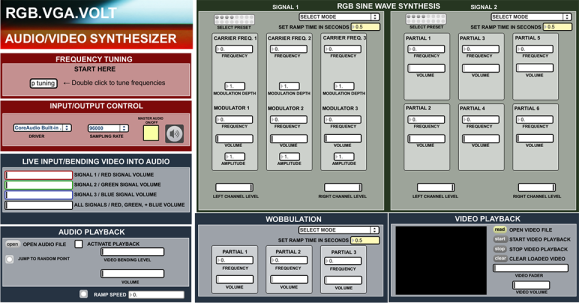
The legacy hardware-based project is called RGB.VGA.VOLT and works by taking an audio signal as an input, crossing some wires, and sending the signal through a synthesizer. The circuit then creates a high-frequency waveform that works especially well for being displayed on VGA. The video can also be channeled back through an audio waveform generator to create a unique sound to go along with the brilliant colors.
[James]’s goals with this project are to generate an aesthetic feeling with his form of art and to encourage others to build upon his work. To that end, he has released the project under an open license, and the project is thoroughly documented on his project site.
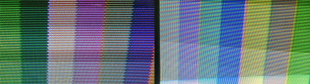
There have been plenty of hacks in the past that have implemented other protocols with VGA or implemented VGA on microcontrollers, but none that have hacked the interface entirely to create something that looks like the Star Gate sequence from 2001: A Space Odyssey. We think it’s a great piece of modern art and a novel use of VGA!
Thanks for the tip, [Kyle]!
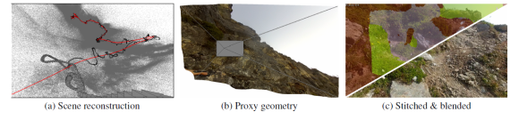 First person video – between Google Glass, GoPro, and other sports cameras, it seems like everyone has a camera on their head these days. If you’re a surfer or skydiver, that might make for some awesome footage. For the rest of us though, it means hours of boring video. The obvious way to fix this is time-lapse. Typically time-lapse throws frames away. Taking 1 of every 10 frames results in a 10x speed increase. Unfortunately, speeding up a head mounted camera often leads to a video so bouncy it can’t be watched without an air sickness bag handy. [Johannes Kopf], [Michael Cohen], and [Richard Szeliski] at Microsoft Research have come up with a novel solution to this problem with
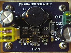 CRTs are the king of displays for any homebrew project. They have everything – high voltages, high vacuums, X-rays, and the potential for a vector display – that makes a project exude cool. Getting an old CRT up and running, though, that’s another story. Never rear, because now