While wireless communications are unquestionably useful in projects, common wireless protocols such as WiFi and Bluetooth peter out after only a number of meters, which is annoying when your project is installed in the middle of nowhere. Moving to an LTE-based or similar mobile solution can help with the range, but this does not help when there’s poor cell coverage, and it tends to use more power. Fortunately, for low-bitrate, low-power wide-area networks (LPWAN) like e.g. sensor networks, there’s a common solution in the form of LoRaWAN, as in long-range wide area network (WAN).
The proprietary LoRa RF modulation technique that underlies LoRaWAN is based on Chirp Spread Spectrum (CSS). This modulation technique is highly resistant to channel noise and fading as well as Doppler shift, enabling it to transmit using relatively low power for long distances. LoRaWAN builds on top of the physical layer provided by LoRa to then create the protocol that devices can then use to communicate with other LoRa devices.
Courtesy of global LoRaWAN gateway and software providers such as The Things Industries and ThingSpeak, it’s possible even as a hobbyist to set up a LoRaWAN-powered sensor network with minimal cost. Let’s take take a look at exactly what is involved in setting up LoRaWAN devices, and what possible alternatives to LoRaWAN might be considered. Continue reading “Casually Chirping Into The World Of LoRaWAN”
 At its core, the project uses an ESP32 and the
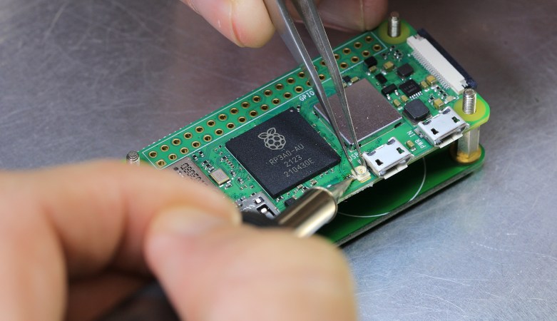
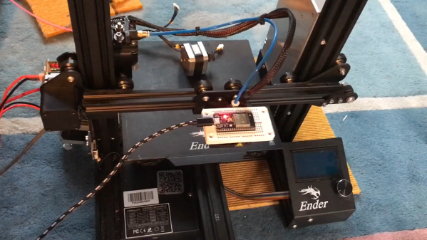
 Granted, based as it is on the gantry of an old 3D printer, [Neumi]’s WiFi scanner has a somewhat limited work envelope. A NodeMCU ESP32 module rides where the printer’s extruder normally resides, and scans through a series of points one centimeter apart. A received signal strength indicator (RSSI) reading is taken from the NodeMCU’s WiFi at each point, and the position and RSSI data for each point are saved to a CSV file. A couple of Python programs then digest the raw data to produce both 2D and 3D scans. The 3D scans are the most revealing — you can actually see a 12.5-cm spacing of signal strength, which corresponds to the wavelength of 2.4-GHz WiFi. The video below shows the data capture process and some of the visualizations.