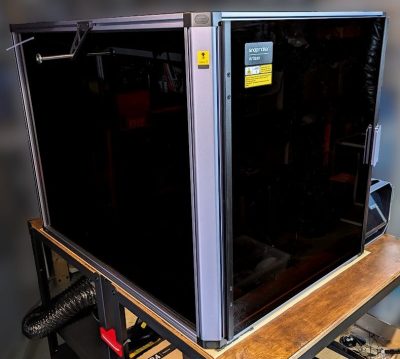
I never feel like I have enough space in my workshop. The promise of consolidating tools to make the most of limited space drew me to the Snapmaker Artisan, a plus-sized 3-in-1 tool combining 3D printer, laser engraver, and CNC machine.
Jacks of all trades may be masters of none, but it is also true that a tool does not need to be a master of its functions to be useful. For many jobs, it enough to simply be serviceable. Does a machine like the Artisan offer something useful to a workshop?
Snapmaker was kind enough to send me an Artisan that I have by now spent a fair bit of time with. While I have come to expect the occasional glitch, having access to multiple functions is great for prototyping and desktop manufacturing.
This is especially true when it allows doing a job in-house where one previously had to outsource, or simply go without. This combo machine does have something to offer, as long as one can give it generous table space in return.
What It Is
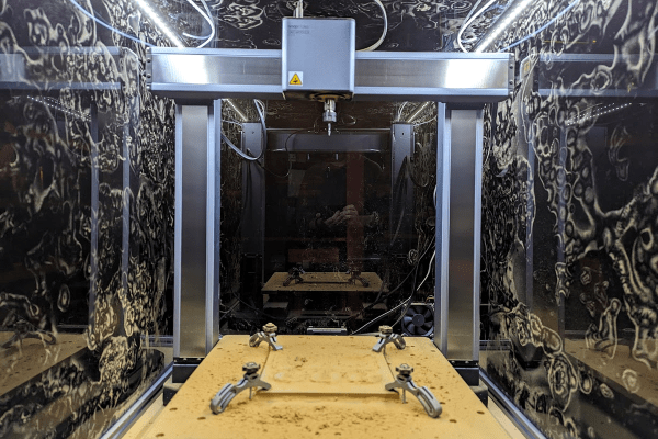
The Artisan is a large dual-extrusion 3D printer, CNC router, and diode-based laser engraver. To change functions, one physically swaps toolheads and beds. Very thankfully, there are quick-change fixtures for this.
Driving the Artisan is Snapmaker’s software Luban (GitHub respository). Named for the ancient Chinese master craftsman, it is responsible for job setup and control. For laser and CNC work, there are convenient built-in profiles for a variety of paper, plastic, leather, and wood products.
The unit is enclosed, nicely designed, and — while I have come to expect the occasional glitch — serviceable at all three of its functions. The size and stature of the machine warrants some special mention, however.
Continue reading “What The Artisan 3-in-1 CNC Offers (If One Has The Table Space)”