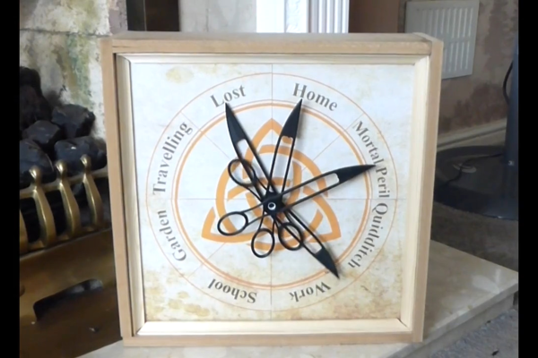
wifi scanner

Visualizing WiFi With A Converted 3D Printer

We all know we live in a soup of electromagnetic radiation, everything from AM radio broadcasts to cosmic rays. Some of it is useful, some is a nuisance, but all of it is invisible. We know it’s there, but we have no idea what the fields look like. Unless you put something like this 3D WiFi field strength visualizer to work, of course.

Granted, based as it is on the gantry of an old 3D printer, [Neumi]’s WiFi scanner has a somewhat limited work envelope. A NodeMCU ESP32 module rides where the printer’s extruder normally resides, and scans through a series of points one centimeter apart. A received signal strength indicator (RSSI) reading is taken from the NodeMCU’s WiFi at each point, and the position and RSSI data for each point are saved to a CSV file. A couple of Python programs then digest the raw data to produce both 2D and 3D scans. The 3D scans are the most revealing — you can actually see a 12.5-cm spacing of signal strength, which corresponds to the wavelength of 2.4-GHz WiFi. The video below shows the data capture process and some of the visualizations.

While it’s still pretty cool at this scale, we’d love to see this scaled up. [Neumi] has already done a large-scale 3D visualization project, using ultrasound rather than radio waves, so he’s had some experience in this area. But perhaps a cable bot or something similar would work for a room-sized experiment. A nice touch would be using an SDR dongle to collect signal strength data, too — it would allow you to look at different parts of the spectrum.

Continue reading “Visualizing WiFi With A Converted 3D Printer”

Copper tubes formed by 3D printed press dies

Can 3D Printed Press Tools Produce Repeatable Parts?

When we think of using a press to form metal we think of large stamps with custom made metal dies under unimaginable hydraulic pressure. It’s unlikely we’d e think of anything 3D printed. And in a commercial environment we’d be right. But your average garage hacker is far more likely to have access to a bench vise and a 3D printer. It’s in this context that [The Shipping Container Garage] has spent considerable time, effort, and money perfecting a process for pressing copper parts with 3D printed dies, which you can watch below the break.

In the quest to make a custom intake manifold for his project car, [The Shipping Container Garage] first made 3D printed jigs for cutting out a manifold flange that bolts to the cylinder head. It’s a process he calls Analog CNC, as all the cutting is done by hand.

Buoyed by his success, he proceeded with the next step: making manifold runners. His metal of choice was copper. While softer than many metals such as steel, he found it too hard. In the video, he describes his method for annealing the copper. Once cooled, two 3D printed dies are pressed into the copper tubes to progressively shape them. Watch the video to find out one of the neatest details of the die itself: how he gets it out!

Of course no matter how clever this all is, it’s useless if it produces poor results. And that’s where the most astounding part of the build is: The parts are all the same within 0.006 inches (0.15mm) of each other, and the parts fit the manifold flange they were made for. Additionally, the die can be used for the duration of the project at hand. For low volume production, this appears to be a viable method. It’ll be interesting to see what others do to iterate these processes to even more advanced stages.

You may also like to see 3D printing used in leather working and in jigs for beautiful circuit sculptures. A big thanks to [JapanFan] for the tip! If you have your own pressing hacks to share, let us know via the Tip Line!

Continue reading “Can 3D Printed Press Tools Produce Repeatable Parts?”

3D Printer Bed Probing Using A Tact Switch And Coin Cell

Inspired by his CNC’s leveling system, [Chuck] built a small PCB to help level his 3D printer and he shares the details in the video you can see below. The idea is simple, the nozzle pushes down on the PCB which has a tact switch underneath. When the switch closes, an LED lights.

In practice, you measure the height of the board and use that for your Z offset, and you are done. Our only concern would be how repeatable the switch is. Granted, most people use a piece of paper and that’s probably not totally repeatable or accurate either. Proper feeler gauges are the “right” way to do it, but we know only a few people who do that.

If you ever look into the repeatability of various Z probes like the proximity sensors or the little pins that drop out of a 3D Touch probe, they aren’t that repeatable. Some people use microswitches, too, which is pretty similar to this approach and is apparently good enough.

The board is available, but it is simple enough that you could create it — or an equivalent — with just about any method you use for your PCBs. [Chuck’s] prototype board was milled. We are always surprised more people don’t use the nozzle itself to sense the bed. Some people go to a lot more trouble than just electrical contact even for CNC.

Continue reading “3D Printer Bed Probing Using A Tact Switch And Coin Cell”

3D Printer Cuts Metal

Every now and then we’ll see a 3D printer that can print an entire house out of concrete or print an entire rocket out of metal. But usually, for our budget-friendly hobbyist needs, most of our 3D printers will be printing small plastic parts. If you have patience and a little bit of salt water, though, take a look at this 3D printer which has been modified to cut parts out of any type of metal, built by [Morlock] who has turned a printer into a 5-axis CNC machine.

Of course, this modification isn’t 3D printing metal. It convers a 3D printer’s CNC capabilities to turn it into a machining tool that uses electrochemical machining (ECM). This process removes metal from a work piece by passing an electrode over the metal in the presence of salt water to corrode the metal away rapidly. This is a remarkably precise way to cut metal without needing expensive or heavy machining tools which uses parts that can easily be 3D printed or are otherwise easy to obtain. By using the 3D printer axes and modifying the print bed to be saltwater-resistant, metal parts of up to 3 mm can be cut, regardless of the type of metal used. [Morlock] also added two extra axes to the cutting tool, allowing it to make cuts in the metal at odd angles.

Using a 3D printer to perform CNC machining like this is an excellent way to get the performance of a machine tool without needing to incur the expense of one. Of course, it takes some significant modification of a 3D printer but it doesn’t need the strength and ridigity that you would otherwise need for a standard CNC machine in order to get parts out of it with acceptable tolerances. If you’re interested in bootstraping one like that using more traditional means, though, we recently featured a CNC machine that can be made from common materials and put together for a minimum of cost.

Continue reading “3D Printer Cuts Metal”

Testing 3D Printed Cutting Blades Is Scary Work

[Ivan Miranda] comes from a land where the shops close on Sundays. Thus, when he found himself in need of a cutting blade, he realised he would have to build his own, or simply wait. He elected to do the former, and we get to enjoy the journey. (Video, embedded below.)

His first attempt was to cut a wooden plank with a 3D-printed cutting blade fitted to a mitre saw. After setting up the mitre saw to cut while he was at a safe distance, [Ivan] elected to test the blade. Alas, it simply melted, and the wood was barely scratched, so [Ivan] went back to the drawing board.

His second attempt was to CNC mill an aluminium blade, which was a full 6 mm thick. The saw needed some modifications to the saw to fit properly, but it was able to cut wood without major drama!

Returning to the 3D-printed concept, [Ivan] suspected reducing the surface speed of the cutting disc could reduce friction-induced heating. This would allow the 3D-printed blade to cut wood without melting, in theory. To achieve this, he built his own basic drop saw using a steel frame and a brushless motor. With a little water spray, and careful control of speed and pressure, the blade was able to slowly chew through a plank of wood. Afterwards, the teeth were almost completely worn down.

The fact is, 3D-printed blades are usually going to be too soft to do any real useful work. However, it’s fun to watch, and that’s good enough for us. If you want something more useful though, consider building your own knives.

Continue reading “Testing 3D Printed Cutting Blades Is Scary Work”

Inconsistent layer heights in a 3D print

An Easy Fix For Inconsistent Layers In Cheap 3D Printers

If there’s one thing you can say about [Stefan] from CNC Kitchen, it’s that he’s methodical when he’s working on an improvement to his 3D printing processes, or when he’s chasing down a problem with a printer. Case in point: this root-cause analysis of extrusion inconsistencies with an entry-level 3D printer.

The printer in question is a Cetus MK3, a printer that found its way onto many benches due to its ridiculously low price and high-quality linear bearings. Unfortunately, there’s still a lot to be desired about the printer, and its tendency for inconsistent layers was chief among [Stefan]’s gripes. Such “blubbiness” can be pinned on any number of problems, but rather than guess, [Stefan] went through a systematic process of elimination to find the root cause. We won’t spoil the ending, but suffice it to say that the problem was subtle, and could probably be the cause of similar problems with other printers. The fix was also easy, and completely mechanical — just a couple of parts to replace. The video below shows the whole diagnosis process, as well as the before and after comparisons. [Stefan] also teases an upcoming treatment on how he converted the Cetus from the stock proprietary control board, which we’re interested in seeing.

If you haven’t checked out any of [Stefan]’s other 3D printing videos, you really should take a look. Whether it’s vibration damping with a concrete paver, salt annealing prints for strength, or using finite element analysis to optimize infills, he’s always got an interesting take on 3D printing.

Continue reading “An Easy Fix For Inconsistent Layers In Cheap 3D Printers”

Erasable Pen Ink Adds Colors To 3D Prints

Changing colors during a 3D print is notoriously difficult. Either you need multiple heads ready to go during the print which increases operating and maintenance costs for your printer, or you need to stop the print to switch the filament and then hope that everything matches up when the print is resumed. There are some workarounds to this problem, but not many of them are as smooth an effortless as this one which uses erasable pen ink to add colors to the filament on the fly.

Erasable pen ink is a thermochromic material that doesn’t get removed from paper when erased like graphite from a pencil. Instead the heat from the friction of erasing causes it to become transparent. By using this property for a 3D print, the colors in the print can be manipulated simply by changing the temperature of the hot end. Of course the team at [Autodrop3d] had quite a learning curve when experimenting with this method, as they had to run the extruder at a much lower temperature than normal to have control over the ink’s color, had to run the print much slower than normal, and were using a very sticky low-temperature plastic for the print.

With all of these modifications to the print setup, there are bound to be some limitations in material and speed, but the results of the project speak for themselves. This allows for stock 3D printers to use this method with no hardware modifications, and the color changes can be done entirely in software. While everyone catches up with this new technology, there are some other benefits to a 3D printer with multiple print heads, though, and some clever ways of doing the switching without too much interruption.

Continue reading “Erasable Pen Ink Adds Colors To 3D Prints”