Like the look of Nixies but they just seem a little overdone? Or perhaps you just don’t want the hassles of a high-voltage power supply? Then maybe these faux-Nixie LED “tube” displays will find a way into your next clock build.
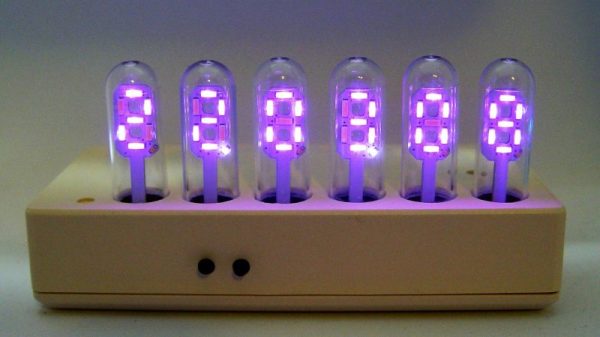
For his 2018 Hackaday Prize entry, [bobricius] decided that what the world needs is a Nixie that’s not a Nixie. To that end, each display is formed by seven surface-mount LEDs soldered to a seven-segment shaped PCB and slipped into a glass tube. The LEDs are in 4014 packages so they’re only 4 millimeters long, but what they lack in size they make up for in brightness. We’re not sure if it’s a trick of the camera, but the LEDs certainly seem to put off a bluish glow that’s reminiscent of vacuum-fluorescent displays — it’s like a Nixie and a VFD all rolled up in one package. The current case, which hides the clock circuitry on the lower part of the PCB, is just plastic, but this would look spiffy in a fine wooden case.
Could this be another Nixie tube killer that never was? Perhaps, but wherever it ends up, we like the look of it, and we’re glad it’s one of the early Hackaday Prize entries. Have you got something to enter in the greatest hardware competition on Earth? If not, get cracking!