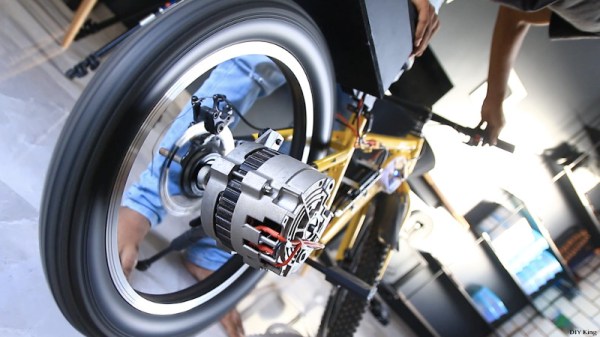
Your garden variety automotive alternator is ripe for repurposing as is, but with a little modification, it can actually be used as a surprisingly powerful brushless motor. Looking to demonstrate the capabilities of one of these rebuilt alternators, [DIY King] bolted one to the back of a old bicycle and got some impressive, and frankly a bit terrifying, results.
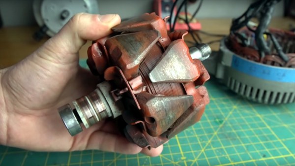
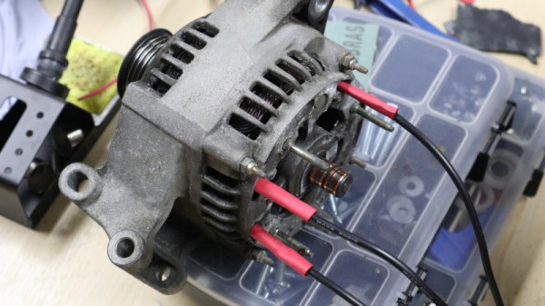
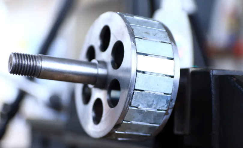
We should say up front that the required modifications to the alternator are quite extensive, so before you get too excited about building your own budget e-bike, you should check out the previous guide [DIY King] put together. The short version is that you’ll need to machine a new rotor and fill it with the neodymium magnets salvaged from hoverboard motors.
Once you’ve got your modified alternator, the rest is relatively easy. The trickiest part of this build looks like it was cutting off the bike’s rear wheel mount and replacing it with a plate that holds the alternator and a pair of reduction gears pulled from a 125cc motorbike. Beyond that, it’s largely electronics.
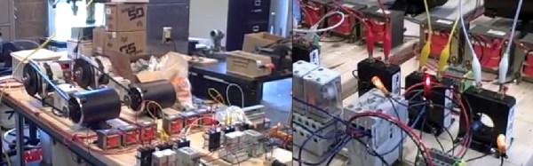
Naturally, you’ll also need a pretty beefy speed controller. In this case [DIY King] is using a 200 amp water-cooled model intended for large RC boats, though interestingly enough, it doesn’t seem he’s actually running any water through the thing. He’s also put together a custom 1,500 watt-hour battery pack that lives in a MDF box mounted under the seat.
To test out his handiwork, [DIY King] took to the streets and was able to get the bike up to 70 km/h (43 MPH) before his courage ran out. He thinks the motor should be able to push it up to 85 km/h, but he says the bike started wobbling around too much for him to really open it up. In terms of range, he calculated that while cruising around at a more palatable 30 km/h (18 MPH), he should be able to get 100 kilometers (62 miles) off of a single charge.
If you like repurposed motors and suicidal bike speeds, you’ll love this build that uses a washing machine motor to push a rider to a claimed 110 km/h. If you’re not worried about speed or range, then this supercapacitor e-bike is certainly worth a look as well.
Continue reading “Modified Car Alternator Powers Speedy DIY E-Bike”