While fixed sensors, relays, and cameras can be helpful in monitoring your home, there are still common scenarios you need to physically go and check something. Unfortunately, this is often the case when you’re away from home. To address this challenge, [PriceLessToolkit] created a guardian bot that can be controlled through Home Assistant.
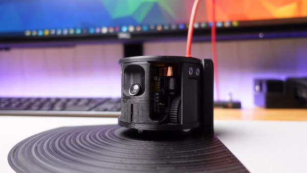
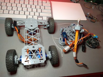
The robot’s body is made from 3D printed components designed to house the various modules neatly. The ESP32 camera module provides WiFi and video capabilities, while the Arduino Pro Mini serves as the bot’s controller. Other peripherals include a light and radar sensor, an LED ring for status display, and a speaker for issuing warnings to potential intruders. The motor controllers are salvaged from two 9-gram servos. The onboard LiPo battery can be charged wirelessly with an integrated charging coil and controller by driving the bot onto a 3D printed dock.
This build is impressive in its design and execution, especially considering how messy it can get when multiple discrete modules are wired together. The rotating caster wheels made from bearings add an elegant touch.
If you’re interested in building your own guard bot, you can find the software, CAD models, and schematics on GitHub. If you’re looking to add other gadgets to your Home Assistant setup, we’ve seen it connect to boilers, blinds, beds and 433 MHz sensors.
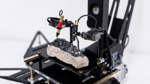
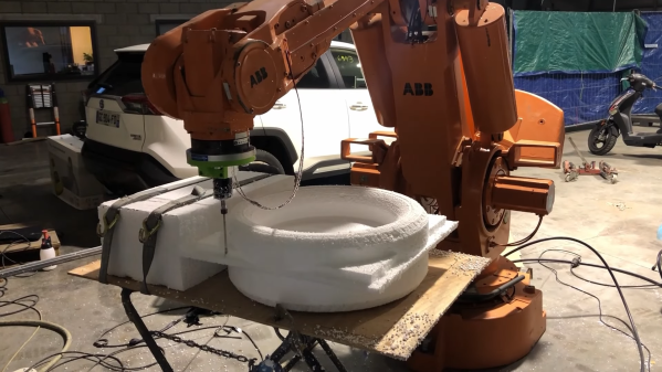
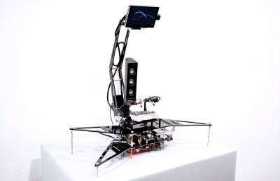 probed per run, but however it works it produces some interesting, almost random results. The premise is that the point-to-point surface resistivity is unpredictable due to the chaotically formed crystals all jumbled up, but somehow uses these measured data to generate some waveshapes vaguely reminiscent of the resistivity profile of the sample, the output of which is then fed into a sound synthesis application and pumped out of a speaker. It certainly looks fun.
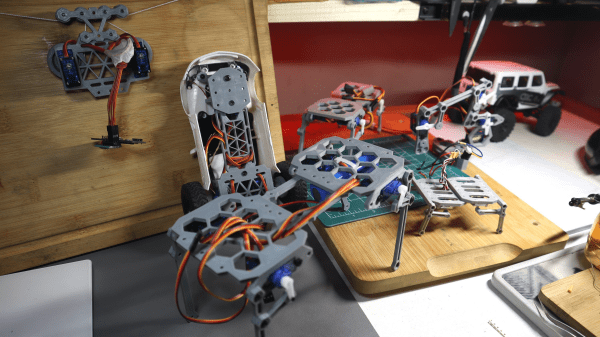
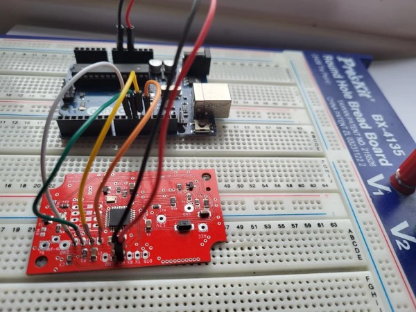
 nRF24L01 boards and build yourself a copy of the remote control [saul] handily provides in