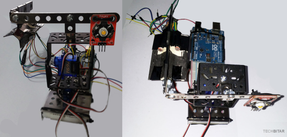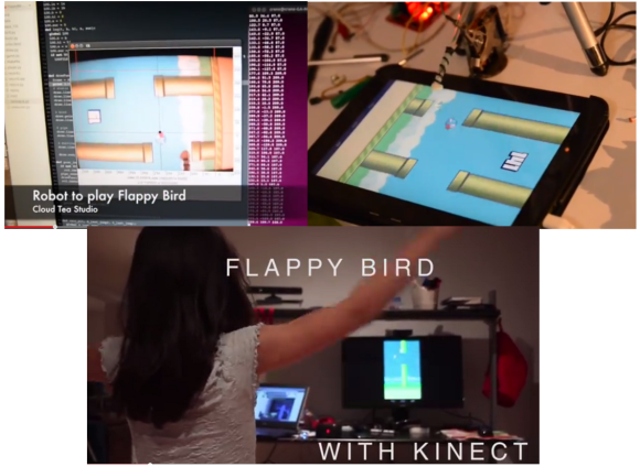
After viral popularity, developer rage quits, and crazy eBay auctions, the world at large is just about done with Flappy Bird. Here at Hackaday, we can’t let it go without showcasing two more hacks. The first is the one that we’ve all been waiting for: a robot that will play the damn game for us. Your eyes don’t deceive you in that title image. The Flappy Bird bot is up to 147 points and going strong. [Shi Xuekun] and [Liu Yang], two hackers from China, have taken full responsibility for this hack. They used OpenCV with a webcam on Ubuntu to determine the position of both the bird and the pipes. Once positions are known, the computer calculates the next move. When it’s time to flap, a signal is sent to an Arduino Mega 2560. The genius of this hack is the actuator. Most servos or motors would have been too slow for this application. [Shi] and [Liu] used the Arduino and a motor driver to activate a hard drive voice coil. The voice coil was fast enough to touch the screen at exactly the right time, but not so powerful as to smash their tablet.
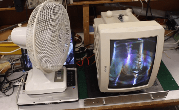
If you would like to make flapping a bit more of a physical affair, [Jérémie] created Flappy Bird with Kinect. He wrote a quick Processing sketch which uses the Microsoft Kinect to look for humans flapping their arms. If flapping is detected, a command is sent to an Android tablet. [Jérémie] initially wanted to use Android Debug Bridge (ADB) to send the touch commands, but found it was too laggy for this sort of hardcore gaming. The workaround is to use a serial connected Arduino as a mouse. The Processing sketch sends a ‘#’ to the Arduino via serial. The Arduino then sends a mouse click to the computer, which is running hidclient. Hidclient finally sends Bluetooth mouse clicks to the tablet. Admittedly, this is a bit of a Rube Goldberg approach, but it does add an Arduino to a Flappy Bird hack, which we think is a perfect pairing.
Continue reading “Computers Playing Flappy Bird. Skynet Imminent. Humans Flapping Arms.”