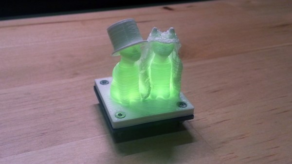
When Are 8 Bits More Than 32?

Whenever we write up a feature on a microcontroller or microcontroller project here on Hackaday, we inevitably get two diametrically opposed opinions in the comments. If the article featured an 8-bit microcontroller, an army of ARMies post that they would do it better, faster, stronger, and using less power on a 32-bit platform. They’re usually right. On the other hand, if the article involved a 32-bit processor or a single-board computer, the 8-bitters come out of the woodwork telling you that they could get the job done with an overclocked ATtiny85 running cycle-counted assembly. And some of you probably can. (We love you all!)

redblue_pillWhen beginners walk into this briar-patch by asking where to get started, it can be a little bewildering. The Arduino recommendation is pretty easy to make, because there’s a tremendous amount of newbie-friendly material available. And Arduino doesn’t necessarily mean AVR, but when it does, that’s not a bad choice due to the relatively flexible current sourcing and sinking of the part. You’re not going to lose your job by recommending Arduino, and it’s pretty hard to get the smoke out of one.

But these days when someone new to microcontrollers asks what path they should take, I’ve started to answer back with a question: how interested are you in learning about microcontrollers themselves versus learning about making projects that happen to use them? It’s like “blue pill or red pill”: the answer to this question sets a path, and I wouldn’t recommend the same thing to people who answered differently.

For people who just want to get stuff done, a library of easy-to-use firmware and a bunch of examples to crib learn from are paramount. My guess is that people who answer “get stuff done” are the 90%. And for these folks, I wouldn’t hesitate at all to recommend an Arduino variant — because the community support is excellent, and someone has written an add-on library for nearly every gizmo you’d want to attach. This is well-trodden ground, and it’s very often plug-and-play.

Continue reading “When Are 8 Bits More Than 32?”

The Flowing Pixels Of Time Wait For No Man

The hourglass dramatically depicts the flow of time; gravity pulling grains of sand inevitably downward. So it is with the Bits of Time project by [Frank Andre]. The pixels drop, stopping only when the battery dies. Or, when your eggs are ready. (Pssst, it’s also on Hackaday.io.)

317661453832865647
Look, Ma! No GIF!

The project starts with a couple of [Frank’s] PixBlocks. A processor is added to one PixBlock to serve as the controller for both after they are connected via the serial bus. A tilt switch, with a debouncing circuit, is connected to an IO pin. This tells the processor the orientation of the box and therefore which way the pixels should flow.

Two  switches set the duration of the timer in 15 second increments. A third starts the timer. When the box is rotated the pixels start flowing in the opposite direction. With code available on GitHub the system can be programmed for other effects such as changing colors, flickering, or even text display.

You’ll agree this is a bit less intimidating than the MacGyver-ish kitchen timer we covered last year.

Continue reading “The Flowing Pixels Of Time Wait For No Man”

There Is No Spoon; Automatic Self Stirring Mug

Sometimes it’s helpful to realize the truth that there is no spoon. At least, not with [Ronaldo]’s automatic self-stirring mug. At first it was just a small propeller in the bottom of the mug that turned on by pushing a button in the handle, but this wasn’t as feature-rich as [Ronaldo] hoped it could be, so he decided to see just how deep the automatic beverage-mixing rabbit hole goes.

The first thing to do was to get a microcontroller installed to handle the operation of the motor. The ATtiny13a was perfect for the job since it’s only using one output pin to control the motor, and can be configured to only draw 0.5 microamps in power-saving mode. This ensures a long life for the two AAA batteries that power the microcontroller and the motor.

As far as operation goes, the motor operates in different modes depending on how many times the button in the handle is pushed. It can be on continuously or it can operate at pre-determined intervals for a certain amount of time, making sure to keep the beverage thoroughly mixed for as long as the power lasts. Be sure to check out the video below for a detailed explanation of all of the operating modes. We could certainly see some other possible uses for more interesting beverages as well.

Continue reading “There Is No Spoon; Automatic Self Stirring Mug”

Father And Son Fix A Scale

It’s awesome when you can tag-team with your dad to fix stuff around the house. [Ilias Giechaskiel], with help from his dad, did a complete refurbishing of a broken bathroom weighing scale, but not before trying to fix it first. The voltage regulator looked bust. Powering the rest of the circuit directly didn’t seem to work, and none of the passives looked suspect. Most of the chips had their markings scratched off and the COB obviously couldn’t be replaced anyway.

Instead of reverse engineering the LCD display, they decided to retain just the sensor and the switches, and replace everything else. The ATtiny85 seemed to have enough IO pins to do the job. But the strain-gauge based load cell, connected in a bridge configuration, did not have a signal span large enough to be measured using the 10 bit ADC on the ATtiny. Instead, they decided to use the HX711 (PDF) – a 24 bit ADC with selectable gain, specifically meant for use in weighing scales. Using a library written for the HX711 allowed interfacing it to the Arduino easy. The display was built using a 4 digit 7 segment display driven by the MAX7219. A slightly modified LEDcontrol library made it easy to hook up the display to the ATtiny. The circuit was assembled on a prototyping board so that it could be plugged in to another Arduino for programming.

Since they were running out of pins, they had to pull out a trick to use a single pin from the ATtiny to act as clock for the display driver and the ADC chip. Implementing the power-on and auto-off feature needed another interesting analog circuit block. Dad did the assembly of the circuit on a prototype board. In hindsight, the lack of IO pins on the ATtiny limited the features they could implement, so the duo are planning to put in an Arduino Nano to improve the hack. If you’re ever stuck with a broken scale, he’s made the schematic (PNG) and code available for use.

A Tiny Servo Motor Controller

If you’re building a moving thing with a microcontroller, you’ll probably want to throw a servo controller in the mix. Driving a servo or two with a microcontroller takes away valuable cycles that just babysit the servo, making sure all the PWM signals are in sync. The thing is, most servo controllers are a massive overkill, and you don’t need that much to control a few servos over a UART. The proof of this is an attiny13 servo controller over on hackaday.io.

[arief] developed his tiny servo controller around one of the tiniest microcontrollers – the ATtiny13. This chip has just 1kB of Flash and 64 Bytes of RAM, but that’s enough to keep a few servos going and listen in to a UART for commands to drive the servo.

The construction of this servo controller board is simple enough – just a single sided board, microcontroller, and a few headers, caps, and resistors. Commands are sent to the ATtiny through a half duplex UART we covered before, with servos responding to simple serial commands.

If you’re building a robot army, this is the board to make. You’re going to need a high-powered controller to take over the world, but there’s no need to bog down that controller by babysitting a few servos.

ATtiny Does 170×240 VGA With 8 Colors

The Arduino is a popular microcontroller platform for getting stuff done quickly: it’s widely available, there’s a wealth of online resources, and it’s a ready-to-use prototyping platform. On the opposite end of the spectrum, if you want to enjoy programming every bit of the microcontroller’s flash ROM, you can start with an arbitrarily tight resource constraint and see how far you can push it. [lucas][Radical Brad]’s demo that can output VGA and stereo audio on an eight-pin DIP microcontroller is a little bit more amazing than just blinking an LED.

[lucas][RB] is using an ATtiny85, the larger of the ATtiny series of microcontrollers. After connecting the required clock signal to the microcontroller to get the 25.175 Mhz signal required by VGA, he was left with only four pins to handle the four-colors and stereo audio. This is accomplished essentially by sending audio out at a time when the VGA monitor wouldn’t be expecting a signal (and [lucas][Rad Brad] does a great job explaining this process on his project page). He programmed the video core in assembly which helps to optimize the program, and only used passive components aside from the clock and the microcontroller.

Be sure to check out the video after the break to see how a processor with only 512 bytes of RAM can output an image that would require over 40 KB. It’s a true testament to how far you can push these processors if you’re determined. We’ve also seen these chips do over-the-air NTSC, bluetooth, and even Ethernet.

Continue reading “ATtiny Does 170×240 VGA With 8 Colors”

Electronic Float Valve Keeps The Horse’s Feet Dry

[Bob] built this simple device that can best be described as an electronic float valve. He was wasting a lot of water from overflowing water troughs and buckets around his farm. He would usually put the hose in the container, turn on the water valve and carry on with his work. By the time he remembered to come back, the area would be flooded. It’s obvious that there’s many different ways to solve a problem. For example, a simple mechanical float valve might have worked, but it’s not horse friendly and liable to get damaged soon.

The electronics is unabashedly minimal. An ATtiny85 controls a relay via a common variety NPN transistor. The relay in turn switches the solenoid valve. A push-button tells the microcontroller to start the water flowing, and when the water level gets high enough that it touches two hose clamps, the micro shuts it off again.

There’s some ghetto engineering going on here. The electronics is driven by a 9V battery, although the relay and the solenoid valve that [Bob] used are both rated for 12V. He’s not even using any sort of voltage regulation for the ATtiny, but instead dropping the voltage with a resistor divider. (We wonder about battery life in the long run.)

He built all of it on perf board and stuffed it inside a small enclosure, with two wires coming out for the level sensor and another two for the solenoid, and it seems to work. Check the video below where [Bob] walks through his build.

While some may point out the many short comings in this build, [Bob] found the one solution that works for him. Sometimes the right solution is what you’ve got on hand, and we’re glad he’s hacking away and sharing his work. And check out this wireless water level sensor that he built some time back.

Continue reading “Electronic Float Valve Keeps The Horse’s Feet Dry”