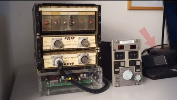
[Adrian Smith] recently scored an avionics module taken from a British Aerospace 146 airliner and ripped it open for our viewing pleasure. This particular aircraft was designed in the early 1980s when the electronics used to feed the various displays in the cockpit were very different from modern designs. This particular box is called a ‘symbol generator’ and is used to generate the various real-time video feeds that are sent to the cockpit display units. Various instruments, for example, the weather radar, feed into it, and it then reformats the video if needed, mixing in any required additional display.
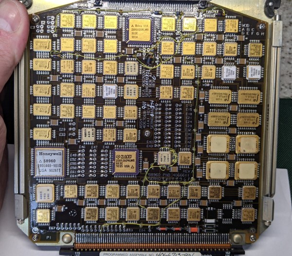
There are many gold-plated chips on these boards, which indicates these may be radiation-hardened versions of familiar devices, most of which are 54xx series logic. 54xx series logic is essentially the same functionally as the corresponding 74xx series, except for the much wider operating temperature range mandated by military and, by extension, commercial aviation needs. The main CPU board appears to be based around the Intel 8086, with some Zilog Z180 compatible processors used on the two video display controller boards. We noted the Zilog Z0853604, which is their counter/timer/GPIO chip. Obviously, there are many custom ASICs produced by Honeywell as well as other special order items that you’ll never find the datasheet for. Now there’s a challenge!
Finally, we note the standard 400 Hz avionics-standard power supply, which, as some may know, is the standard operating frequency for the AC power system used within modern aircraft systems. The higher frequency (compared to 50 or 60 Hz) means the magnetic components can be physically smaller and, therefore, lighter for a given power handling capability.
We see a lot of avionics teardowns, likely because they’re fascinating. Here’s some more British military gear, an interesting RF distance measuring box from the 1970s, and finally, some brave soul building their own avionics gear. What could possibly go wrong?
Continue reading “Teardown Of An Aircraft Video Symbol Generator”