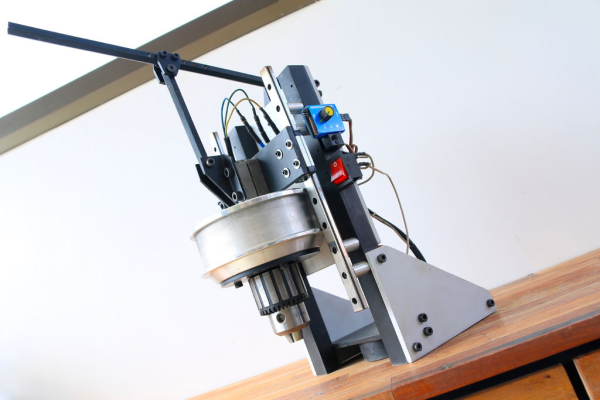
If you need to drill metal in tight places, the magnetic drill press, or mag drill is your BFF. The idea here is that a drill press with an electromagnetic base can go anywhere, and even drill horizontally if need be. If you don’t need to use one often, but want one anyway, why not build one out of e-waste?
 [DIY KING 00] built this mag drill starting with the motor from a hoverboard. While these three-phase brushless motors have a lot of torque to offer reuse projects like this, they’re not designed to be particularly fast.
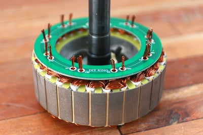
He was able to make it about three times faster by cutting the windings apart and reconnecting them in parallel instead of series. He designed a simple PCB to neatly tie all the connections back together and added an electronic speed control (ESC) from an R/C car.
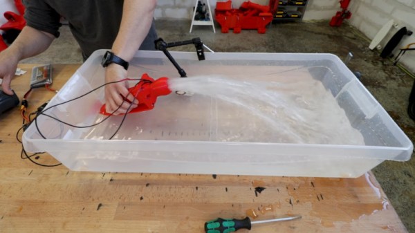
Reluctant to give up the crown, he made his own three-coil electromagnetic base, using a drill to wind magnet wire around temporary chuck-able cores. The coils are then potted in epoxy to keep out dust and drilling debris. Everything runs from two large LiPo batteries, and he can get about 15 minutes of high-torque drilling done before they’re dead. Can you feel the electromagnet pulling you past the break to check out the build and demo video?
Depending on what you’re doing, you might get away with a magnetic vise instead.
Continue reading “Hoverboard Grows Up, Becomes Magnetic Drill Press”