[Ludic Science] shows us the basic principles that lie behind the humble boost converter. We all take them for granted, especially when you can make your own boost converter or buy one for only a few dollars, but sometimes it’s good to get back to basics and understand exactly how things work.
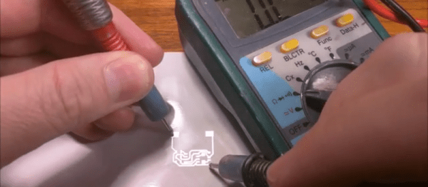
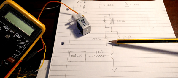
The circuit in question is probably as simple as it gets when it comes to a boost converter, and is not really a practical design. However it helps visualize what is going on, and exactly how a boost converter works, using just a few parts, a screw, enameled wire, diode, capacitor and a push button installed on a board.
The video goes on to show us the science behind a boost converter, starting with adding a battery from which the inductor stores a charge in the form of an electromagnetic field. When the button is released, the magnetic field collapses, and this causes a voltage in the circuit which is then fed through a diode and charges the capacitor a little bit. If you toggle the switch fast enough the capacitor will continue to charge, and its voltage will start to rise. This then creates a larger voltage on the output than the input voltage, depending on the value of the inductor. If you were to use this design in a real life application, of course you would use a transistor to do the switching rather than a push button, it’s so much faster and you won’t get a sore finger.
This is very basic stuff, but the video gives us a great explanation of what is happening in the circuit and why. If you liked this article, we’re sure you’ll love Hackaday’s own [Jenny List] explain everything you need to know about inductors.
(updated thanks to [Unferium] – I made a mistake about the magnetic field collapsing when the button is pressed , When in reality it’s when the button is released that this happens. Apologies for confusion.)