Open-source Circuit Simulation

For simple circuits, it’s easy enough to grab a breadboard and start putting it together. Breadboards make it easy to check your circuit for mistakes before soldering together a finished product. But if you have a more complicated circuit, or if you need to do response modeling or other math on your design before you start building, you’ll need circuit simulation software.

While it’s easy to get a trial version of something like OrCAD PSpice, this software doesn’t have all of the features available unless you’re willing to pony up some cash. Luckily, there’s a fully featured free and open source circuit simulation software called Qucs (Quite Universal Circuit Simulator), released under the GPL, that offers a decent alternative to other paid circuit simulators. Qucs runs its own software separate from SPICE since SPICE isn’t licensed for reuse.

Qucs has most of the components that you’ll need for professional-level circuit simulation as well as many different transistor models. For more details, the Qucs Wikipedia page lists all of the features available, as does the project’s FAQ page. If you’re new to the world of circuit simulation, we went over the basics of using SPICE in a recent Hack Chat.

Thanks to [Clovis] for the tip!

Print, Rinse, Wear. Nanowire Circuits For Your Microfibre Clothing.

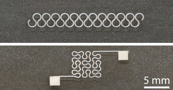
While our bodies are pretty amazing, their dynamic nature makes integrating circuits into our clothing a frustrating process.  Squaring up against this challenge, a team of researchers from North Carolina State University have hit upon a potential boon for wearable electronics: silver nanowires capable of being printed on flexible, stretchy substrates.

It helps that the properties of silver nanowires lend themselves to the needs of wearable circuits — flexible and springy in their own right — but are not without complications. Silver nanowires tend to clog print nozzles during printing, so the research team enlarged the nozzle and suspended the nanowires in a water-soluble solvent, dramatically cutting the chance of clogging. Normally this would have a negative impact on precision, but the team employed electrostatic force to draw the ink to the desired location and maintain print resolution. Once printed, the solvent is rinsed away and the wearable circuit is ready for use.

By controlling print parameters — such as ink viscosity and concentration — the team are able to print on a wide variety of materials. Successful prototypes thus far include a glove with an integrated heating circuit and an electrocardiograph electrode, but otherwise the size of the printer is the only factor limiting the scale of the print. Until this technique becomes more widely available, interested parties might have to put their stock into more homebrew methods.

[Thanks for the tip, Qes!]

MicroPython Learns A New Trick – ISP For AVRs

One of the reasons why the Arduino became so popular was the ability to program it with ease. It meant the end of big parallel programmers that would cost an arm and a leg. The latest installment of CircuitPython from [Lady Ada] and the team over at Adafruit is a library for programming AVR microcontrollers without a dedicated PC.

For the uninitiated, in-system programming or ISP for AVR controllers employ the SPI bus to write the compiled binary to the flash memory of the controller. The discount on the number of pins used itself is a benefit though getting the timings right was a bit tricky in the good old days. Most dedicated ISPs handle this nicely, though they are normally slaves to a host PC where an ‘upload’ button initiates the process.

With CircuitPython (a derivative of MicroPython), programming microcontrollers does not require going through the code-compile-flash cycle. It can be run on a number of processors, however, AVRs are not among them so this neat little library offers the next best thing. Wire-up an Atmega328P or ATmega2560 to a board like the ESP8266 that does run CircuitPython, and you can write firmware on the fly.

There is a complete tutorial on the subject thanks to [Phillip Torrone] and [Lady Ada] which includes some demo files for testing out the functionality. This opens up a lot of possibilities where OTA firmware updates for an AVR co-processor. We expect to see some keychain AVR programmers in the near future taking a hint from the ESP8266 based Two-Factor Authentication featured previously.

Electromagnet-Powered Pendulum

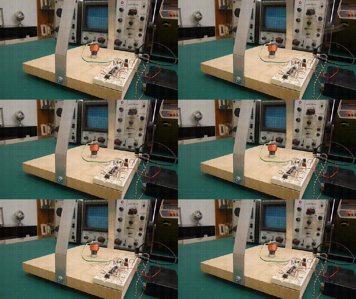
We’re always happy to see hackers inspired to try something different by what they see on Hackaday. To [SimpleTronic] has a project that will let you stretch your analog electronics skills in a really fun way. It’s an electromagnet pendulum analog circuit. Whether you’re building it, or just studying the schematics, this is a fun way to brush up on the non-digital side of the craft.

The pendulum is a neodymium magnet on the head of a bolt, dangling on a one foot aluminium chain. Below, a Hall Effect sensor rests atop an electromagnet — 1″ in diameter, with 6/8″ wire coiled around another bolt. As the pendulum’s magnet accelerates towards the electromagnet’s core, the Hall effect sensor registers an increase in voltage. The voltage peaks as the pendulum passes overhead, and as soon as the Hall Effect sensor detects the drop in voltage, the electromagnet flicks on for a moment to propel the pendulum away. This circuit has a very low power consumption, as the electromagnet is only on for about 20ms!

The other major components are a LM358N op-amp, a CD4001B quad CMOS NOR gate, and IRFD-120 MOSFET. [SimpleTronic] even took the time to highlight each part of the schematic in order to work through a complete explanation.

Continue reading “Electromagnet-Powered Pendulum”

A Lesson On Zener Regulators

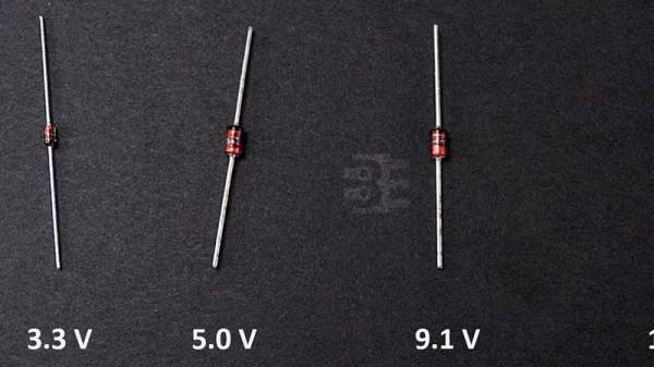
For the longest time, Zener diode regulators have been one of those circuits that have been widely shared and highly misunderstood. First timers have tried to use it to power up their experiments and wondered why things did not go as planned. [James Lewis] has put up a worth tutorial on the subject titled, “Zener Diode makes for a Lousy Regulator”  that clarifies the misconceptions behind using the device.

[James Lewis] does an experiment with a regulator circuit with an ESP8266 after a short introduction to Zener diodes themselves. For the uninitiated, the Zener diode can operate in the reverse bias safely and can do so at a particular voltage. This allows for the voltage across the device to be a fixed value.

This, however, depends on the current flowing through the circuit which in turn relies on the load. The circuit will work as expected for loads the draw a small amount of current. This makes it suitable for generating reference voltages for microcontrollers and such.

To make a Zener into a “proper” voltage regulator, you just need to buffer the output with an amplifier of some kind. A single transistor is the bare minimum, but actually can work pretty well. You might also add a capacitor in parallel with the Zener to smooth out some of its noise.

Zener diodes are wonderful little devices and write-ups like these are indispensable for beginners and should be shared more often like the Zener and Schottky Tutorial and Diodes as a Switch.


Non-standard circuit boards

Non-standard Circuits: Jazz For Electrons

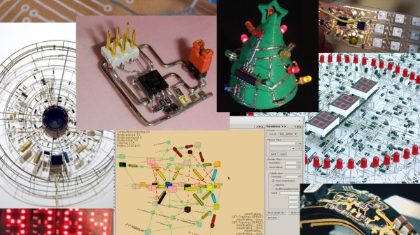
How creative are you when you make your circuit boards? Do you hunt around for different materials to use for the board? As long as it’s an insulator and can handle the heat of a soldering iron, then anything’s fair game. Or do you use a board at all? Let’s explore some options, both old favorites and some you may not have seen before, and see if we can get our creative juices flowing.

Transparent Circuit Boards

Let’s start with the desire to show more circuit and less board. For that we can start with [CNLohr]’s circuits on glass, usually microscope slides. What’s especially nice about his is that he provides detailed videos of the whole process, including all the failed things he tried along the way. Since he didn’t start with copper clad board, he instead glued his copper sheet to the glass using Loctite 3301. That was followed by the usual etching process, though with plenty of gotchas along the way.

In the end, he made a number of circuits, including an LED clock with the LEDs on the glass itself, and even attempted leading the community in making a glass keytar. The latter didn’t work out, but the resulting glass circuits are a work of art anyway.

What about making a transparent circuit board out of acrylic? [Frank Zhao] attempted just that by laser cutting troughs into the acrylic for the traces, and then drawing in nickel ink. But something in the ink ate into the acrylic, and as if that wasn’t bad enough, the voltage drop across the nickel was too high for his circuit. Suggestions were made in the comments for how to solve these problems, but unless we missed it, we haven’t seen another attempt yet.

But we’ve only just begun. What if you wanted even more transparency?

Continue reading “Non-standard Circuits: Jazz For Electrons”

Control Thy LED

In a previous article, I discussed LEDs in general and their properties. In this write-up, I want to give some examples of driving LEDs and comparing a few of the most commonly used methods. There is no “one size fits all” but I will try and generalize as much as possible. The idea is to be able to effectively control the brightness of the LED and prolong their life while doing it. An efficient driver can make all the difference if you plan to deploy them for the long-haul. Let’s take a look at the problem and then discuss the solutions. Continue reading “Control Thy LED”