Foam is certainly an indispensable raw material for various craft and construction projects. Any serious sculptor however, inevitably grows tired of grinding through a foam block using a simple preheated utensil. The next step up, is to assemble a simple but thoroughly effective hot wire cutting contraption, formed out of a thin guitar wire held taut on a “C” shaped mounting frame. Finally, the addition of some electronics to regulate the power delivery makes this simple tool useful for most settings.
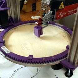
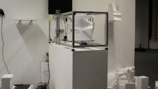
[Freddie] has taken this basic idea a step further, by building a complete multi-axis CNC foam cutter intended as an interactive exhibit on computational art. The CNC has the traditional three Cartesian axes but the platform hosting the foam piece can also rotate, introducing an additional degree of freedom. As this is indented to be controlled by attendees, there is no G-code in the mix, rather the inputs of an Xbox controller are applied directly to the work piece.
What is very interesting is how the resulting tool path is visualised and displayed. [Freddie] explains that while the user input tool path could be generated and displayed as equivalent G-code, it does not capture and convey the inherent organic nature of the finished pieces. The solution [Freddie] came up with is to display the toolpath much like a series of musical notes!
We would have loved to have a go at this machine in person, but seeing that isn’t possible in the current circumstances, you can either build a simpler machine we featured earlier or [Freddie] could perhaps fire up a camera and let us control it via the interweb, with a live video feed ofcourse!
Continue reading “Interactive CNC Foam Cutter Churns Out Abstract Art”