Count Your Fans With This Stylish ESP8266 Display

Continuous self-affirmation is a vital component to the modern lifestyle. Of course you know the world loves you, but exactly how much do they love you? Checking your phone every few minutes to see if you’ve gained any followers is gauche, and perhaps more to the point, doesn’t let you show off when you’ve got visitors over. In the modern era, the up-and-coming social media star needs a stylish way to display just how popular they are for the world to see.

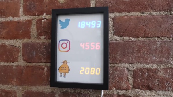
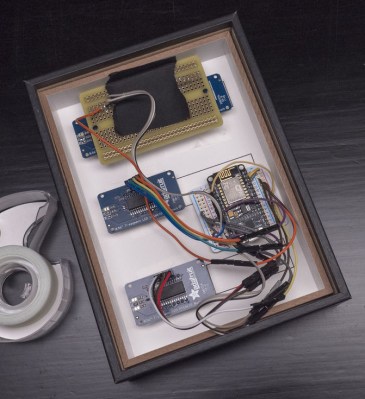
That’s the idea behind this very slick social media counter created by [Becky Stern]. Built into a standard shadow box frame and using LED displays glowing through a printed piece of paper, the finished product looks more like modern art than the usual hacker fare.

The counter is powered by a NodeMCU, but you could drop in your favorite variant of the ESP8266 and things would work more or less the same. For the displays, [Becky] is using four Adafruit 7-Segment LED modules, which are easily controlled via I2C which keeps the wiring to a minimum.

It’s interesting to note that since her follower count on Twitter has already hit five digits, two of the display modules are used next to each other for that particular service. Her Instructables and Instagram counters only have one display each however, limiting her counts on those services to 9,999 each. There’s probably something to be learned here in terms of the relative follower counts you can expect on the different social networks if you’re targeting your content to the hacker and maker crowd, but we’ll leave the analysis to those with a better handle on such matters.

Hardware aside, [Becky] spends a lot of time in the video talking about the code she’s come up with to pull her stats from the various services and push them out to the LED displays at a regular interval. It’s nice to see so much attention and explanation given to the software side of a project like this, as more often than not you’re left to your own to figure out what the source code is doing.

This project is quite similar to the YouTube Play Button hack we covered a few months back, but the addition of multiple social networks in one device is a nice improvement over the basic concept.

Continue reading “Count Your Fans With This Stylish ESP8266 Display”

Count YouTube Subscribers With This Red Play Button Award

Professional YouTubers live and die by the number of subscribers they have. It seems like a brutal way to make a living to us, but to each his own. Still, if you’re going to do it, you might as well do it right, and keeping track of how you’re doing with this Play Button Award subscriber counter might make sense. Or it might drive you nuts.

YouTuber [ibuynewstuff] has reached the vaunted 100,000 subscriber mark, the number required to earn the Silver Play Button award. Sadly, 100k is the bare minimum needed to get YouTube’s attention, and tales of waiting for months for the award to arrive are not uncommon. [ibuynewstuff] worked around the issue by 3D-printing his own temporary play button badge. Mounted to a picture frame with an ESP8266 and an 8 x 80 LED display behind a diffuser, [ibuynewstuff] can keep track of his progress toward the Gold Play Button award at 1,000,000 subs. Hopefully, his Silver award will arrive before then.

Want to replicate this but would rather have something a little more permanent than a plastic play button? Try casting your own Copper Play Button award.

Continue reading “Count YouTube Subscribers With This Red Play Button Award”

You Know You Can Do That With A 555

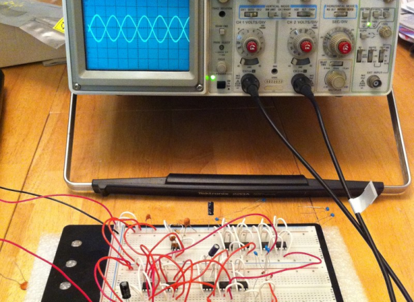
Hardly a week goes by that we don’t post a project where at least one commenter will lament that the hacker could have just used a 555. [Peter Monta] clearly gets that point of view. For a 555 design contest, he created both digital logic gates and an op amp, all using 555 chips. We can’t quite imagine the post apocalyptic world where the only surviving electronic components are 555 chips, but if that day were to come, [Peter] is your guy.

Using the internal structure of the 555, [Peter] formed a basic logic gate, an inverter, latches, and more. He also composed things like counters and seven-segment decoders. He had a very simple 4-bit CPU design in Verilog that he was going to attempt until he realized it would map into almost 400 chips (half of that if you’d use a dual 555, but still). If you built this successfully, we would probably post it, by the way.  You can see a video of the digital logic counter, below.

Continue reading “You Know You Can Do That With A 555”

Tea For Two: A Tiny Tea Timer

The ATtiny85 microcontroller doesn’t have all that much of anything: 8 KB of flash, an 8-bit architecture, and only eight pins (three of which are taken up with power and reset duties). And that’s exactly what makes it a great fit for tiny little projects.

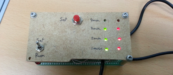
[Mimile]’s Tea Timer has a switch, a button, eight LEDs, and a buzzer. Flip the switch to “set” and button presses run through the desired steeping times. Flip it to “run” and you’re timing. The LEDs blink and the buzzer plays “Tea for Two” in squawky square waves. Wonderful!

But wait, how to control all of this I/O with just five pins? With one pin each for the two switches and one for the buzzer, that leaves only two pins for the eight LED display. [Mimile]’s fun solution is to use a binary counter (a 74HC393) and the remaining two lines to count and reset. That means toggling a pin very fast 255 times to light up all the LEDs. That’s a bizarre way to go, but we like it!

Hackaday has proven unable to resist the siren song of the ATtiny85. Whether teaching it to swear, to speak I2C, or to transmit analog TV signals, there’s just something about this cute little chip that invites you to test your mettle.

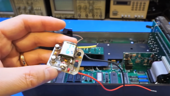
Characterizing A Cheap 500MHz Counter Module

An exciting development over the last few years has been the arrival of extremely cheap instrumentation modules easily bought online and usually shipped from China. Some of them have extremely impressive paper specifications for their price, and it was one of these that caught the eye of [Carol Milazzo, KP4MD]. A frequency counter for under $14 on your favourite online retailer, and with a claimed range of 500 MHz. That could be a useful instrument in its own right, and with a range that significantly exceeds the capabilities of much more expensive bench test equipment from not so long ago.

Just how good is it though, does it live up to the promise? [Carol] presents the measurements she took from the device, so you can see for yourselves. She took look at sensitivity, VSWR, and input impedance over a wide range, after first checking its calibration against a GPS-disciplined standard and making a fine adjustment with its on-board trimmer.

In sensitivity terms it’s a bit deaf, requiring 0.11 Vrms for a lock at 10 MHz. Meanwhile its input impedance decreases from 600 ohms at the bottom of its range to 80 ohms at 200 MHz, with a corresponding shift in VSWR. So it’s never going to match a high-end bench instrument from which you’d expect much more sensitivity and a more stable impedance, but for the price we’re sure that’s something you can all work around. Meanwhile it’s worth noting from the pictures she’s posted that the board has unpopulated space for an SPI interface header, which leaves the potential for it to be used as a logging instrument.

We think it’s worth having as much information as possible about components like this one, both in terms of knowing about new entrants to the market and in knowing their true performance. So if you were curious about those cheap frequency counter modules, now thanks to [Carol] you have some idea of what they can do.

While it’s convenient to buy a counter module like this one, of course there is nothing to stop you building your own. We’ve featured many over the years, this 100MHz one using a 74-series prescaler or this ATtiny offering for example, or how about this very accomplished one with an Android UI?

Digital Counter From Stuff You Have In Your Junk Drawer

In vehicle racing, a properly tuned suspension is essential for making good time around the track. Weekend Race Warrior [Julian], thought that his right rear suspension might be bottoming out when making hard left turns. After thinking about it for a while, he came up with a super simple way to measure how many times his suspension bottoms out during a lap: a digital counter made from a calculator.

There are two types of calculators out there, one is good for this project and the other won’t work. To figure out which one you have, type in 1+1=. All calculators should display 2. Then, press the = button again. Some calculators will continue to show 2, but some will change to 3, then 4 and so on as many times as the = button is pressed. This is the type of calculator this project requires.

[Julian] opened up his calculator and soldered a pair of wires across the = button terminals. After a hole was drilled in the case for the wires to exit, the calculator was put back together. To count how often his suspension bottomed out, a normally open limit switch was installed on the car at a point where it would be triggered when the suspension bottomed out. The 2 added wires coming out of the modified calculator connect to that switch. Switch presses now emulate a = button press. Before starting a lap, 1+1= is pressed to display 2. At the end of the lap, if the suspension bottomed out, the switch would be triggered and the displayed value would increase. Remember to subtract 2 from that value to get the total number of events that occurred.

A mechanical switch makes this a great application for counting when things move a certain way but there are some more options. Connecting the switch-side of a relay to the calculator allows [Julian] to count brake presses (via the break light signals) or count how often his boost pressure goes over a certain amount (using a pressure switch).

Diode Steering And Counting With A 555

While you’re not likely to see this technique used very much today, there’s a lot you can do with a 555, some logic chips, and a handful of diodes. [Fran] is here with a great example of using these simple parts to build a circuit that counts to zero, using parts you can probably find under your workbench.

[Fran] was inspired to build this diode counter from one of [Dave]’s Mailbags and [Colin Mitchell]’s 555 circuit book. The 555 is the standard component found in every parts drawer, but since we have tiny microcontrollers that cost the same as a 555, we’re not seeing the artistry of a simple timer chip and a few logic chips much these days.

This circuit began with a 555 attached to a 4017B decade counter. Simply by tying a few LEDs to the output of the 4017, [Fran] made a bunch of LEDs light up in sequence. Cool, but nothing unexpected. The real trick uses a few diodes and six LEDs to build a scanner – a line of LEDs that will blink from left to right, then right to left. Impressive, and with a little more circuitry it’s a Larson Scanner, as seen in Battlestar Galactica and Knight Rider.

The real trick for this technique comes when [Fran] pulls out a piece of protoboard, several dozen diodes, and seven old transistors to have a seven-segment display count from zero to nine. The 4017 simply counts out on ten pins, and each of these pins is wired to a bunch of diodes for each segment in the display. Add in a few resistors and a transistor, and [Fran] replicated what’s inside a seven-segment driver with discrete parts.

If counting to zero isn’t enough proof that you can do a whole lot with some diodes and logic chips, how about programming an Atari 2600 with one?

Video below.

Continue reading “Diode Steering And Counting With A 555”