There’s a tremendous amount of value in using pre-built, known-good development environments. It saves you hours of potential headaches when things aren’t working. Is the bug in the hardware or the software? If you bought a dev kit, you can be pretty sure it’s your software. But sometimes using a dev kit also feels like there’s a black box in the system. [Kevin] wanted to peer inside the black box, so he ordered a tray of cheap STM32F103 chips on eBay, and did the rest himself.
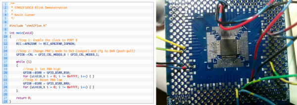
“The rest” isn’t all that much, but figuring that out is half the battle. [Kevin] soldered the TQFP chip onto a breakout board, added some decoupling capacitors, and connected four pins up to a dirt-cheap ST-Link programmer clone. The rest of the article describes the toolchain he used to compile for and program the chip. The end result is, natch, a blinking LED.
If you’re a bit experienced with microcontrollers and want to dive head-first into an ARM chip, [Kevin]’s writeup is just the ticket. In a single (long) blog post, he walks you through all the steps. If this is your first rodeo, you might be tempted to cheese out and buy a pre-built board on eBay (search “STM32F103” and you’ll find many options to choose from) and we don’t think that’s a bad idea either. Still, there’s just something to be said for the confidence that you’ll have once you’ve built the whole system from scratch.