Learning SDR And DSP Hack Chat

Join us on Wednesday, November 11th at noon Pacific for Learning SDR and DSP Hack Chat with Marc Lichtman!

“Revolution” is a term thrown about with a lot less care than it probably should be, especially in fields like electronics. It’s understandable, though — the changes to society that have resulted from the “Transistor Revolution” or the “PC Revolution” or more recently, the “AI Revolution” have been transformative, often for good and sometimes for ill. The common thread, though, is that once these revolutions came about, nothing was ever the same afterward.

Such is the case with software-defined radio (SDR) and digital signal processing (DSP). These two related fields may not seem as transformative as some of the other electronic revolutions, but when you think about it, they really have transformed the world of radio communications. SDR means that complex radio transmitters and receivers, no longer have to be implemented strictly in hardware as a collection of filters, mixers, detectors, and amplifiers; instead, they can be reduced to a series of algorithms running on a computer.

Teamed with DSP, SDR has resulted in massive shifts in the RF field, with powerful, high-bandwidth radio links being built into devices almost as an afterthought. But the concepts can be difficult to wrap one’s head around, at least when digging beyond the basics and really trying to learn how SDR and DSP work. Thankfully, Dr. Marc Lichtman, an Adjunct Professor at the University of Maryland, literally wrote the book on the subject. “PySDR: A Guide to SDR and DSP using Python” is a fantastic introduction to SDR and DSP that’s geared toward those looking to learn how to put SDR and DSP to work in practical systems. Dr. Lichtman will stop by the Hack Chat to talk about his textbook, to answer your questions on how best to learn about SDR and DSP, and to discuss what the next steps are once you conquer the basics.

join-hack-chatOur Hack Chats are live community events in the Hackaday.io Hack Chat group messaging. This week we’ll be sitting down on Wednesday, November 11 at 12:00 PM Pacific time. If time zones baffle you as much as us, we have a handy time zone converter.

Click that speech bubble to the right, and you’ll be taken directly to the Hack Chat group on Hackaday.io. You don’t have to wait until Wednesday; join whenever you want and you can see what the community is talking about.

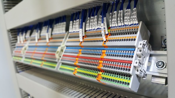
[Banner image credit: Dsimic, CC BY-SA 4.0, via Wikimedia Commons]

Continue reading “Learning SDR And DSP Hack Chat”

Hackaday Links Column Banner

Hackaday Links: October 11, 2020

If you’re interested in SDR and digital signal processing but don’t know where to start, you’re in luck. Ben Hillburn, president of the GNU Radio Project, recently tweeted about an online curriculum for learning SDR and DSP using Python. The course was developed by Dr. Mark Lichtman, who was a lead on GNU Radio, and from the look of it, this is the place to go to learn about putting SDRs to use doing cool things. The course is chock full of animations that make the concepts clear, and explain what all the equations mean in a way that’s sure to appeal to practical learners.

It’s not much of a secret that the Hackaday community loves clocks. We build clocks out of everything and anything, and any unique way of telling time is rightly applauded and celebrated on our pages. But does the clock motif make a good basis for a video game? Perhaps not, but that didn’t stop Clock Simulator from becoming a thing. To “play” Clock Simulator, you advance the hands of an on-screen clock by pressing a button once per second. Now, thanks to Michael Dwyer, you don’t even have to do that one simple thing. He developed a hardware cheat for Clock Simulator that takes the 1PPS output from a GPS module and wires it into a mouse. The pulse stream clicks the mouse once per second with atomic precision, rendering the player irrelevant and making the whole thing even more pointless. Or perhaps that is the point.

Maybe we were a little hard on Clock Simulator, though — we can see how it would help achieve a Zen-like state with its requirement for steady rhythm, at least when not cheating. Another source of Zen for some is watching precision machining, and more precise, the better. We ran into this mesmerizing video of a CNC micro-coil winder and found it fascinating to watch, despite the vertical format. The winder is built from a CNC lathe, to the carriage of which a wire dispenser and tensioning attachment have been added. The wire is hair-fine and passes through a ruby nozzle with a 0.6 mm bore, and LinuxCNC controls the tiny back and forth motion of the wire as it winds onto the form. We don’t know what the coil will be used for, but we respect the precision of winding something smaller than a matchhead.

Dave Jones over at EEVblog posted a teardown video this week that goes to a place few of us have ever seen: inside a processor module for an IBM System/390 server. These servers earned the name “Big Iron” for a reason, as everything about them was engineered to perform. The processor module Dave found in his mailbag was worth $250,000 in 1991, and from the look of it was worth every penny. From the 64-layer ceramic substrate supporting up to 121 individual dies to the stout oil-filled aluminum enclosure, everything about this module is impressive. We were particularly intrigued by the spring-loaded copper pistons used to transfer heat away from each die; the 2,772 pins on the other side were pretty neat too.

Here’s an interesting question: what happens if an earthquake occurs in the middle of a 3D printing run? It’s probably not something you’ve given much thought, but it’s something that regular reader Marius Taciuc experienced recently. As he relates, the magnitude 6.7 quake that struck near Kainatu in Papua New Guinea (later adjusted to a 6.3 magnitude) resulted in a solid 15 seconds of shaking at his location, where he was printing a part on his modified Mendel/Prusa i2. The shaking showed up clearly in the part as the machine started swaying with the room. It’s probably not a practical way to make a seismograph, but it’s still an interesting artifact.

Intuition About Signals And Systems

Signals and systems theory is a tough topic. Terms like convolution and impulse response can be hard to understand on a visceral level and most books that talk about these things emphasize math over intuition. [Discretised] has a YouTube channel that already has several videos that promise to tackle these topics with “minimum maths, maximum intuition.” We particularly noticed the talks on convolution and impulse response.

We think that often math and intuition don’t always come together. It is one thing, for example, to know that E=I times R, and power is I times E, but it is another to realize that a half-watt transmitter delivers 5V into a 50Ω load and that one watt will take just over 7V into that same load.

The example used is computing how much smoke you can expect to create by setting off fireworks. We presume the math models are notional since we imagine a real model would be pretty complex and involve things like wind data. But it still makes a nice example.

If you don’t know anything about the topic, these might not be the right ones to try to learn the basics. But we do applaud people sharing their intuition on these complex subjects.

Continue reading “Intuition About Signals And Systems”

A Mini SDR Receiver Using An Audio DSP

Software defined radio or SDR is the most exciting frontier in the field of radio, transferring as it does all signal functions from the analogue to the digital domain. Radios using SDR techniques can be surprisingly straightforward and easy to understand, and [Ray Ring]’s little SDR receiver manages to combine this with the novel use of an audio DSP rather than a computer to perform its SDR functions.

The front end is a conventional enough direct conversion design with an Si5531 clock generator providing I and Q phase-shifted local oscillator signals to a TS3A5017 analogue switch used as a mixer. An unexpected presence is an LTC6252 op-amp as an RF amplifier, but the special part comes after the I and Q baseband signals have been filtered. The SDR part of this receiver is an audio DSP, but it’s one that might not be an immediate choice. The Spin Semiconductor FV-1 is a dedicated digital reverb chip for musical effects boxes, but it comes with the feature that its internal DSP core can access custom code from an external ROM. [Ray] has written his own code for demodulation of AM, USB, and LSB signals rather than musical effects, and used the device’s left and right audio channels to process I and Q quadrature signals. The use of a single purpose chip to do something its designers never intended gives it the essence of a good hack, and we’re mightily impressed at his spotting the potential for an SDR in a musical effect. Hear it in action in the video below the break.

Meanwhile if the operation of a receiver such as this one is a mystery to you, we published a handy primer back in 2017.

Continue reading “A Mini SDR Receiver Using An Audio DSP”

DSP Spreadsheet: Talking To Yourself Using IQ

We’ve done quite a bit with Google Sheets and signal processing: we’ve generated signals, created filters, and computed quadrature signals. We can pull all that together into an educational model for two SDRs talking to each other, but it’s going to require two parts: modulation and demodulation. Guess what? We can do that with a spreadsheet.

The first step is to generate a reference clock for the carrier. You’ll need a cosine wave (I) and sine wave (Q). Of course, you also need the time base. That’s columns A-C in the spreadsheet and works like other signal generation we’ve seen.

Continue reading “DSP Spreadsheet: Talking To Yourself Using IQ”

DSP Spreadsheet: IQ Diagrams

In previous installments of DSP Spreadsheet, we’ve looked at generating signals, mixing them, and filtering them. If you start trying to work with DSP, though, you’ll find a topic that always rears its head: IQ signals. It turns out, these aren’t as hard as they appear at first and, as usual, we’ll tackle them in a spreadsheet.

What does IQ stand for? The I stands for “in phase” and the Q stands for quadrature. By convention, the I signal is a cosine wave and the Q signal is a sine wave. Another way to say that is that the I and Q signals are 90 degrees out of phase. By manipulating the amplitude of I and Q, you can create complex modulation or, conversely, demodulate signals. We’ll see a spreadsheet that shows that completely next time.

Continue reading “DSP Spreadsheet: IQ Diagrams”

DSP Spreadsheet: Frequency Mixing

Circuit simulation and software workbooks like Matlab and Jupyter are great for being able to build things without a lot of overhead. But these all have some learning curve and often use clever tricks, abstractions, or library calls to obscure what’s really happening. Sometimes it is clearer to build math models in a spreadsheet.

You might think that spreadsheets aren’t built for doing frequency calculation and visualization but you’re wrong. That’s exactly what they’re made for — performing simple but repetative math and helping make sense of the results.

In this installment of the DSP Spreadsheet series, I’m going to talk about two simple yet fundamental things you’ll need to create mathematical models of signals: generating signals and mixing them. Since it is ubiquitous, I’ll use Google Sheets. Most of these examples will work on any spreadsheet, but at least everyone can share a Google Sheets document. Along the way, we’ll see a neat spreadsheet trick I should probably use more often.

Continue reading “DSP Spreadsheet: Frequency Mixing”