Intuition About Signals And Systems

Signals and systems theory is a tough topic. Terms like convolution and impulse response can be hard to understand on a visceral level and most books that talk about these things emphasize math over intuition. [Discretised] has a YouTube channel that already has several videos that promise to tackle these topics with “minimum maths, maximum intuition.” We particularly noticed the talks on convolution and impulse response.

We think that often math and intuition don’t always come together. It is one thing, for example, to know that E=I times R, and power is I times E, but it is another to realize that a half-watt transmitter delivers 5V into a 50Ω load and that one watt will take just over 7V into that same load.

The example used is computing how much smoke you can expect to create by setting off fireworks. We presume the math models are notional since we imagine a real model would be pretty complex and involve things like wind data. But it still makes a nice example.

If you don’t know anything about the topic, these might not be the right ones to try to learn the basics. But we do applaud people sharing their intuition on these complex subjects.
Continue reading “Intuition About Signals And Systems”

A Mini SDR Receiver Using An Audio DSP

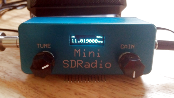
Software defined radio or SDR is the most exciting frontier in the field of radio, transferring as it does all signal functions from the analogue to the digital domain. Radios using SDR techniques can be surprisingly straightforward and easy to understand, and [Ray Ring]’s little SDR receiver manages to combine this with the novel use of an audio DSP rather than a computer to perform its SDR functions.

The front end is a conventional enough direct conversion design with an Si5531 clock generator providing I and Q phase-shifted local oscillator signals to a TS3A5017 analogue switch used as a mixer. An unexpected presence is an LTC6252 op-amp as an RF amplifier, but the special part comes after the I and Q baseband signals have been filtered. The SDR part of this receiver is an audio DSP, but it’s one that might not be an immediate choice. The Spin Semiconductor FV-1 is a dedicated digital reverb chip for musical effects boxes, but it comes with the feature that its internal DSP core can access custom code from an external ROM. [Ray] has written his own code for demodulation of AM, USB, and LSB signals rather than musical effects, and used the device’s left and right audio channels to process I and Q quadrature signals. The use of a single purpose chip to do something its designers never intended gives it the essence of a good hack, and we’re mightily impressed at his spotting the potential for an SDR in a musical effect. Hear it in action in the video below the break.

Meanwhile if the operation of a receiver such as this one is a mystery to you, we published a handy primer back in 2017.

Continue reading “A Mini SDR Receiver Using An Audio DSP”

DSP Spreadsheet: Talking To Yourself Using IQ

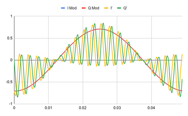
We’ve done quite a bit with Google Sheets and signal processing: we’ve generated signals, created filters, and computed quadrature signals. We can pull all that together into an educational model for two SDRs talking to each other, but it’s going to require two parts: modulation and demodulation. Guess what? We can do that with a spreadsheet.

The first step is to generate a reference clock for the carrier. You’ll need a cosine wave (I) and sine wave (Q). Of course, you also need the time base. That’s columns A-C in the spreadsheet and works like other signal generation we’ve seen.

Continue reading “DSP Spreadsheet: Talking To Yourself Using IQ”

DSP Spreadsheet: IQ Diagrams

In previous installments of DSP Spreadsheet, we’ve looked at generating signals, mixing them, and filtering them. If you start trying to work with DSP, though, you’ll find a topic that always rears its head: IQ signals. It turns out, these aren’t as hard as they appear at first and, as usual, we’ll tackle them in a spreadsheet.

What does IQ stand for? The I stands for “in phase” and the Q stands for quadrature. By convention, the I signal is a cosine wave and the Q signal is a sine wave. Another way to say that is that the I and Q signals are 90 degrees out of phase. By manipulating the amplitude of I and Q, you can create complex modulation or, conversely, demodulate signals. We’ll see a spreadsheet that shows that completely next time.

Continue reading “DSP Spreadsheet: IQ Diagrams”

DSP Spreadsheet: Frequency Mixing

Circuit simulation and software workbooks like Matlab and Jupyter are great for being able to build things without a lot of overhead. But these all have some learning curve and often use clever tricks, abstractions, or library calls to obscure what’s really happening. Sometimes it is clearer to build math models in a spreadsheet.

You might think that spreadsheets aren’t built for doing frequency calculation and visualization but you’re wrong. That’s exactly what they’re made for — performing simple but repetative math and helping make sense of the results.

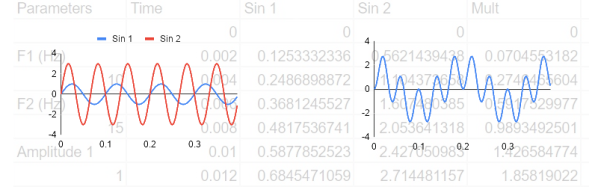
In this installment of the DSP Spreadsheet series, I’m going to talk about two simple yet fundamental things you’ll need to create mathematical models of signals: generating signals and mixing them. Since it is ubiquitous, I’ll use Google Sheets. Most of these examples will work on any spreadsheet, but at least everyone can share a Google Sheets document. Along the way, we’ll see a neat spreadsheet trick I should probably use more often.

Continue reading “DSP Spreadsheet: Frequency Mixing”

DSP Spreadsheet: FIR Filtering

There’s an old saying: Tell me and I forget, teach me and I may remember, involve me and I learn. I’m guilty of this in a big way — I was never much on classroom learning. But if I build something or write some code, I’m more likely to understand how it works and why.

Circuit simulation and software workbooks like Matlab and Jupyter are great for being able to build things without a lot of overhead. But these all have some learning curve and often use clever tricks, abstractions, or library calls to obscure what’s really happening. Sometimes it is easier to build something in a spreadsheet. In fact, I often do little circuit design spreadsheets or even digital design because it forces me to create a mathematical model which, in turn, helps me understand what’s really going on.

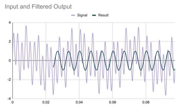
In this article I’m going to use Google Sheets — although you could do the same tricks in just about any spreadsheet — to generate some data and apply a finite impulse response (FIR) filter to it. Of course, if you had a spreadsheet of data from an instrument, this same technique would work, too.

Continue reading “DSP Spreadsheet: FIR Filtering”

C++ Reverbs From A Matlab Design

The guitar ‘Toing’ sound from the ’70s was epic, and for the first time listener it was enough to get a bunch of people hooked to the likes of Aerosmith. Reverb units were all the rage back then, and for his DSP class project, [nebk] creates a reverb filter using Matlab and ports it to C++.

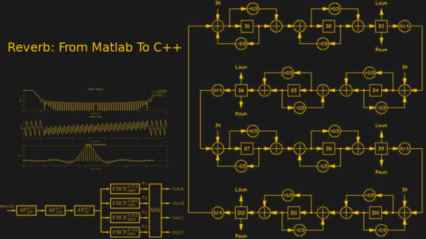
Digital reverb was introduced around the 1960s by Manfred Schroeder and Ben Logan. The system consists of essentially all pass filters that simply add a delay element to the input signal and by clubbing a bunch together and then feeding them to a mixer. The output is then that echoing ‘toing’ that made the ’80s love the guitar so much. [Nebk]’s take on it enlists the help of the Raspberry Pi and C++ to implement the very same thing.

In his writeup, [nebk] goes through the explaining the essentials of a filter implementation in the digital domain and how the cascaded delay units accumulate the delay to become a better sounding system. He also goes on to add an FIR low pass filter to cut off the ringing which was consequent of adding a feedback loop. [nebk] uses Matlab’s filter generation tool for the LP filter which he includes the code for. After testing the design in Simulink, he moves to writing the whole thing in C++ complete with the filter classes that allows reading of audio files and then spitting out ‘reverbed’ audio files out.

The best thing about this project is the fact that [nebk] creates filter class templates for others to play with. It allows those who are playing/working with Matlab to transition to the C++ side with a learning curve that is not as steep as the Himalayas. The project has a lot to learn from and is great for beginners to get their feet wet. The code is available on [GitHub] for those who want to give it a shot and if you are just interested in audio effects on the cheap, be sure to check out the Ikea Reverb Plate that is big and looks awesome.