Just In Time For The Holidays – Laser Cut Gift Boxes

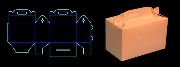
If you’re anything like us, there’s a good chance that you plan on making (rather than buying) a few of your Christmas presents this year. But if past history is any indication of future success, we’ll most like run out of time and succumb to the quick-fix that only a big-box store can provide. But at least the packaging can be home made with this cool set of templates to get you started on your way.

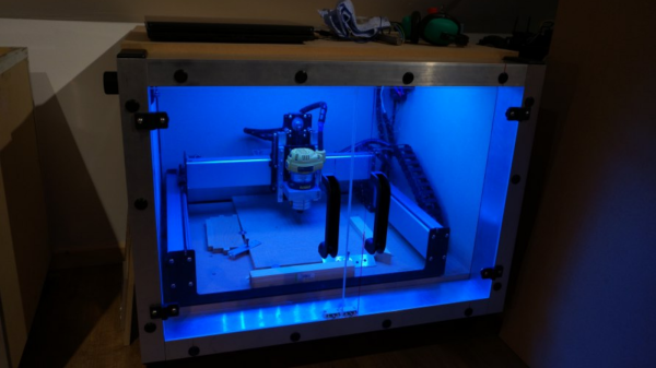
The [Rabbitlaserusa] link has many more gift box templates than just the one shown here. In fact, we like this idea so much, we almost wonder if some of the examples could be turned into project enclosures if the right material was used – but we’re getting ahead of ourselves. We recognize that not everyone has an easy, affordable way to access a laser cutter, so just remember that these designs could be printed out and then cut by hand as well.

And, if your looking for some last minute gift ideas for kids, check out [Rabbitlaserusa] 3D animal gig saw puzzles here.


Hackaday Links: November 22, 2015

There’s a new documentary series on Al Jazeera called Rebel Geeks that looks at the people who make the stuff everyone uses. The latest 25-minute part of the series is with [Massimo], chief of the arduino.cc camp. Upcoming episodes include Twitter co-creator [Evan Henshaw-Plath] and people in the Madrid government who are trying to build a direct democracy for the city on the Internet.

Despite being a WiFi device, the ESP8266 is surprisingly great at being an Internet of Thing. The only problem is the range. No worries; you can use the ESP as a WiFi repeater that will get you about 0.5km further for each additional repeater node. Power is of course required, but you can stuff everything inside a cell phone charger.

I’ve said it before and I’ll say it again: the most common use for the Raspberry Pi is a vintage console emulator. Now there’s a Kickstarter for a dedicated tabletop Raspi emulation case that actually looks good.

Pogo pins are the go-to solution for putting firmware on hundreds of boards. These tiny spring-loaded pins give you a programming rig that’s easy to attach and detach without any soldering whatsoever. [Tom] needed to program a few dozen boards in a short amount of time, didn’t have any pogo pins, and didn’t want to solder a header to each board. The solution? Pull the pins out of a female header. It works in a pinch, but you probably want a better solution for a more permanent setup.

Half of building a PCB is getting parts and pinouts right. [Josef] is working on a tool to at least semi-automate the importing of pinout tables from datasheets into KiCad. This is a very, very hard problem, and if it’s half right half the time, that’s a tremendous accomplishment.

Last summer, [Voja] wrote something for the blog on building enclosures from FR4. Over on Hackaday.io he’s working on a project, and it’s time for that project to get an enclosure. The results are amazing and leave us wondering why we don’t see this technique more often.

How To Build Beautiful Enclosures From FR4 — Aka PCBs

Most hobbyists say that it is easier to build a functional prototype of an electronic device, than to make the enclosure for it. You could say that there are a lot of ready-made enclosures on the market, but they are never exactly what you need. You could also use a 3D printer to build a custom enclosure, but high-end 3D printers are too expensive, and the cheaper ones produce housings which are often not robust enough, and also require a lot of additional treatment.

Another way is to build the enclosure out of FR4, a material which is commonly used in PCB production. Such enclosures are low-cost, with thin walls but yet very strong, nice looking, pleasant to the touch and have excellent thermal and moisture stability. FR4 offers some more possibilities – efficient wiring with no wires inside the housing, integrated UHF or SHF antennas or RFID coils, capacitive switches, electrical shielding, selective semi-transparency, water or air tightness, and even integration of complex mechanical assemblies.

Here I shall explain the process of building those “magic” enclosures. It is based on nearly fifty years of personal experience and more than a hundred enclosures, built for most of my projects. Here are two examples – this case for a hardware password manager is just a few centimeters long, while the other one (protective transportation cover for my son’s synthesizer) measures 125cm (about 49 inches), and yet both of them are strong enough to withstand a grown man standing on top of them.

The global approach is simple – you take the sheet of single-sided copper clad FR4, cut it and solder the parts together. That sounds simple, but there are a lot of details which should be met if you want to get top results. Please read about them carefully. You might be tempted to skip some of the steps described here, but if you do so, you will most likely end up being disappointed with the results.

Continue reading “How To Build Beautiful Enclosures From FR4 — Aka PCBs”

Behold! The Most Insane Crowdfunding Campaign Ever

Hold on to your hats, because this is a good one. It’s a tale of disregarding the laws of physics, cancelled crowdfunding campaigns, and a menagerie of blogs who take press releases at face value.

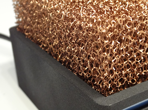
Meet Silent Power (Google translation). It’s a remarkably small and fairly powerful miniature gaming computer being put together by a team in Germany. The specs are pretty good for a completely custom computer: an i7 4785T, GTX 760, 8GB of RAM and a 500GB SSD. Not a terrible machine for something that will eventually sell for about $930 USD, but what really puts this project in the limelight is the innovative cooling system and small size. The entire machine is only 16x10x7 cm, accented with a very interesting “copper foam” heat sink on top. Sounds pretty cool, huh? It does, until you start to think about the implementation a bit. Then it’s a descent into madness and a dark pit of despair.

There are a lot of things that are completely wrong with this project, and in true Hackaday fashion, we’re going to tear this one apart, figuring out why this project will never exist.

Continue reading “Behold! The Most Insane Crowdfunding Campaign Ever”

Designing And Printing A Custom Enclosure

enclosure

So you know how to design a circuit board, assemble the parts, and have a functional device at the end of a soldering session. Great, but if you want to use that device in the real world, you’re probably going to want an enclosure, and Tupperware hacked with an Exacto knife just won’t cut it. It’s actually not that hard to design a custom enclosure for you board, as [Glen] demonstrates with a custom 3D printed project box.

[Glen]’s board, a quad RS-422 transmitter with a PMOD connector, was designed in Eagle. There are a vast array of scripts and plugins for this kind of mechanical design work, including the EagleUP plugins that turn an Eagle PCB into a 3D object that can be imported into SketchUp.

Taking measurements from Eagle, [Glen] designed a small project box that fits the PCB. A few standoffs were added, and the board itself was imported into SketchUp. From there, all he needed to do was to subtract the outline of the connectors from the walls of then enclosure for a custom-fit case. Much better than Tupperware, and much easier than designing a laser cut enclosure.

Once the enclosure was complete, [Glen] exported the design as an STL, ready for 3D printing or in his case, sending off to Shapeways. Either way, the result is a custom enclosure with a perfect fit.


Designing A Front Panel For A DIY Project

DIY Front Panel


When building a one-off DIY project, appearances tend to be the least of our priorities. We just want to get the device working, and crammed into some project case. For those that like to build nicer looking prototypes [JumperOne] came up with a slick method of building a custom front panel for your DIY project.

The first step is to get the dimensions correct. You CAD tool will generate these from your design. [JumperOne] took these measurements into Inkscape, an open source vector graphics tool. Once it’s in Inkscape, the panel can be designed around the controls. This gets printed out and aligned on a plastic enclosure, which allows the holes to be marked and drilled.

With the electronics in place, the front panel gets printed again on a general purpose adhesive sheet. Next up is a piece of cold laminating film, which protects the label. Finally, holes are cut for the controls. Note that the display and LEDs are left covered, which allows the film to diffuse the light. The final result looks good, and can provide all the needed instructions directly on the panel.

[Thanks to Ryan for the tip]

Cobalt RaQ Retrofit Help Geek Up Your Entertainment Center

cobalt-raq-jukebox

Even network engineers who toil away in hot server rooms (which aren’t actually all that hot because they’re well climate controlled) deserve nice things. That’s why Cobalt came out with these gorgeous front bezels for their rack mounted equipment… around twenty years ago. [Geekmansworld] is reviving the look, but he’s not hiding it away in a server rack. He scrapped the guts and used the front bezel and controls as part of his media server.

His first new addition to the case was a pair of hard drives which connect to an eSATA hub also stored in the enclosure. He buttoned it up and gave it a test run. Everything worked smoothly and he hopes that it will continue that way without overheating when the summer rolls around again.

Of course a dead front bezel is no fun so he cut off the portion of the original circuit board which hosts the buttons seen on the right. These buttons now connect to a U-HID board which turns the button presses into mouse or keyboard inputs using a USB connection. The original display was swapped out for a backlit character LCD. The LEDs to the left are a refit which turns the status indicators into a VU-Meter. See the entire thing at work after the break.

Continue reading “Cobalt RaQ Retrofit Help Geek Up Your Entertainment Center”